OWNER’S MANUAL
9
10
MAX. RECOMMENDATION ROTOR SIZE
MODEL NAME TYPE ROTOR SIZE
KILLAH/ STITCH/
STORM/ ROGUE
POST 203(mm)
SLOPE POST 180(mm)
SPACE IS 203(mm)
RENEGADE POST 180(mm)
TITAN15/ TITAN POST 180(mm)
CHAMP series POST 180(mm)
F1RST series POST 180(mm)
AERIAL Rebound series
AERIAL series
POST 180(mm)
PULSE series POST 180(mm)
VOGUE IS 180(mm)
VIVAir IS 180(mm)
15QR: 15mm Aluminum Quickly Release axle
1. Slide hub into the legs and line up with axle holes.
2. Apply grease or Anti seize to the entire 15mm axle.
3. Slide the 15mm Axle into the fork/hub from the left hand side (Disc side).
4. Gently turn the axle clockwise to connect to the lock bolt threads in the right hand leg.
5. Turn the 15QR axle to the xed position; tighten the 15QR axle to 15Nm by press the
lever.
6. If need to adjust the lever position of the 15QR axle, pull open the lever of 15QR axle
then remove the grub screw then adjust the lock bolt with 15QR axle to the proper
position.
7. 7.Install the grub screw into the ‘’location dimples’’ of the lock bolt, tighten the 15QR
axle to 15Nm by press the lever again. (Taking care to keep the ‘’location Dimples’’ in
line with the grub screw hole in the fork. You should be able to see the location Dimple
by looking down the hole.
8. Check that Disc brake operates correctly.
SPECIAL INSTRUCTION FOR 20MM HUB AND QR
INSTALLATION
Installing 20mm Front Hub
1. Slide hub (including 20mm cones) into the legs and line up with axle holes.
2. Apply grease or Anti seize to the entire 20mm axle.
3. Slide the 20mm Axle into the fork/hub from the left hand side (Disc side).
4. Gently turn the axle clockwise to connect to the axle threads in the right hand leg.
5. Once located V fully tighten the axle to 12-15Nm using an 8mm Hex key.
6. Apply grease or anti seize to the Right Hand side Axle lock bolt.
7. Gently screw-in the lock bolt into the 20mm axle end.
8. Hold the left hand side of the axle with a 8mm Hex key and fully tighten the right hand
side lock bolt to 12-15Nm using a 2nd 8mm Hex Key.
9. Check that Disc brake operates correctly.
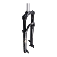
Installing QR type Front Hub
1. Identify Adaptor and parts
2. Carefully install grub-screws 3 turns into fork legs-ensuring they are not cross-
threaded. (Note: this may initially be harder than normal, as grub screw may have to
clear some paint residue in the threads from the leg.)
3. Remove the grub-screws.
4. Lightly grease the outside of the adaptors.
5. Install the right hand adaptor into the Right hand leg, taking care to keep the ‘’location
dimples’’ in line with the grub screw hole in the fork. You should be able to see the
location dimple by looking down the fork leg hole.
6. Install the grub screw and tighten gently until it contacts the adaptor.
7. Back-out the grub screw 2 full turns, and the gently try to turn the adaptor.
You should feel a small amount play, between the grub screw head and the adaptor ‘’location
dimple’’-and your small turn should be stopped by the grub screw. If your rotation is not
stopped, it means the grub screw head is not entering the ‘’location dimple’’. Retry. Once you
are convinced that the grub screw is lined up with the ‘’location dimple’’ you can fully tighten
the grub screw to 3Nm.
SAFETY NOTE: It is IMPORTANT that the grub screws are correctly located into the adaptor
dimples ‘’IF NOT’’ the adaptors could rotate and cause a failure.
8. Repeat with Left Hand Adaptor.
SPECIAL INSTRUCTION FOR 15MM QR AXLE INSTALLATION
Instruction of disassemble 20mm thru axle:
1.Use 8mm allen key to loose the bolt in the right leg.
2.Use 8mm allen key to loose the 20mm thru axle.
WARNING
1. Before disassembly of the ‘’function system’’, it is strongly recommended to
take it to an RST dealer. The authorized RST dealers will provide qualified
technicians with proper tools and training to perform service correctly. Improper
disassembly may damage the product and lead to failure of human injury.
2. Before completing maintenance, please make sure all screws have been
securely tightened according the correct torque settings to avoid any human
injury.