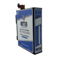
The 435NBX-NNA1 is an ASCII to PLC Gateway, designed to seamlessly connect ASCII devices to various Programmable Logic Controllers (PLCs). This device supports a range of PLCs including ControlLogix, CompactLogix, FlexLogix, MicroLogix, PLC5E, and SLC, particularly those featuring a NetENI module.
Function Description:
The primary function of the 435NBX-NNA1 gateway is to facilitate communication between ASCII devices and PLCs. It acts as an intermediary, translating data between the ASCII protocol used by devices like barcode scanners, weigh scales, and printers, and the proprietary protocols of different PLCs. This enables data exchange, allowing ASCII devices to send data to the PLC for processing and control, and allowing the PLC to send commands or data back to the ASCII devices. The gateway supports both ASCII to PLC and PLC to ASCII communication, providing a bidirectional data flow.
Important Technical Specifications:
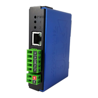
- Power: The gateway operates on an 8-24 VDC power source. It draws approximately 175mA at 12V.
- Dimensions: The physical dimensions of the gateway are 3.88 inches by 2.57 inches by 1.06 inches (all dimensions in inches).
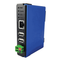
- Mounting: It is designed for DIN Rail mounting, ensuring easy integration into industrial control panels.
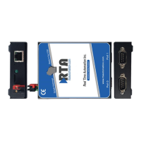
- Serial Ports: The device features a configurable serial port (Port 0) that supports both RS232 and RS485 communication modes.
- Ethernet Link: The gateway supports 100 Mbps, Half Duplex Ethernet communication.
- IP Settings: It can be configured to obtain an IP address automatically (DHCP) or use a static IP address.
- Communication Modes: The gateway supports both "Connected (Class 3 Explicit)" and "Unconnected (UCMM)" communication modes for interaction with PLCs. Connected mode relies on reserved resources for data transfer, while Unconnected mode shares resources, potentially leading to message timeouts in busy networks.
- Heartbeat Tag/File: A configurable heartbeat tag/file (INT Data Type Tag for RSLogix5000 Family, N Register for RSLogix500 Family) can be used to monitor communication status with the PLC.
- ASCII Message Termination: Users can define character count, timer, and delimiters for ASCII message termination. Character count can range from 1-4096 characters, and the timer from 0-300000 ms. Delimiters can be configured for both start and end of messages.
- Message Queue: The gateway includes a message queue with a configurable size (0-20 messages). The queue full behavior can be set to either "Discard New Data" or "Overwrite Oldest Data."
- NULL Character Handling: Options are available for handling NULL characters in data conversion, including "None" (no additional conversion) or "Remove NULL" (removes all NULL characters).
- Error Definitions: The manual provides a comprehensive list of error codes (e.g., 0x00 for Success, 0x01 for Controller Slot Doesn't Exist, 0x02 for Resource unavailable, 0x03 for Invalid parameter value, 0x04 for Incorrect Tag Data Type, 0x05 for Incorrect Controller Type, 0x0F for Privilege violation, 0x10 for Device state conflict, 0x11 for Reply data too large, 0x12 for Fragmentation of a primitive value, 0x13 for Not enough data, 0x14 for Attribute not supported, 0x15 for Too much data, 0x16 for Object does not exist, 0x17 for Server fragmentation sequence, 0x18 for No stored attribute data, 0x19 for Store operation failure, 0x1A for Routing failure, request packet too large, 0x1B for Routing failure, response packet too large, 0x1C for Missing attribute list entry data, 0x1D for Invalid attribute value list, 0x1E for Embedded server error, 0x1F for Vendor specific error, 0x20 for Invalid parameter, 0x21 for Write once value or medium already written, 0x22 for Invalid reply received, 0x23 for Buffer Overflow, 0x24 for Message format error, 0x25 for Key failure in path, 0x26 for Path size invalid, 0x27 for Unexpected attribute, 0x28 for Invalid member ID, 0x29 for Member not settable, 0x2C for Attribute not gettable). These codes help in diagnosing communication issues.
Usage Features:
- Web-based Configuration: The gateway is configured through a web interface, accessible via a standard web browser. This allows for remote setup and management.
- Device Configuration: Users can edit device description, IP settings (IP address, subnet, default gateway), and Ethernet link settings.
- PLC Configuration: This section allows users to select the PLC type, IP address, controller slot, and communication mode. It also includes settings for inter-message delay and heartbeat tag/file.
- ASCII Configuration: This is where the core ASCII communication parameters are defined, including data type (STRING, SINT, INT), tag/file name, character count, timer, delimiters (start and end), message queue size and behavior, and NULL character handling.
- Diagnostics: The web interface provides diagnostic pages to monitor PLC status, ASCII status, device status, and communication attempts. It also includes diagnostic counters for ASCII events (delimiter, length, timeout, discards), read/write handshake messages to/from PLC, and read/write ASCII messages to/from PLC.
- Test Message Functionality: Users can send test messages from the web interface to both the PLC and the ASCII device to verify communication.
- Security Configuration: The gateway offers security features, including log out timer, username, password, and admin information.
- Firmware Upgrade: Firmware can be upgraded through the web interface by uploading a firmware file.
- SD Card Functionality: The gateway supports an SD card for saving and restoring configuration, as well as for IP setup. This allows for easy deployment and backup.
- User-Defined Tags: For RSLogix 5000, users can create user-defined string tags to accommodate varying message lengths.
- Program Scope Tags: The manual provides guidance on accessing Program Scope Tags in RSLogix 5000, which is useful for organizing and managing tags within specific programs.
Maintenance Features:
- Reboot Functionality: The gateway can be rebooted from the web interface to apply configuration changes or resolve issues.
- Intelligent Reset Button: A physical reset button on the gateway, accessible via a pinhole, allows for resetting to default DHCP IP settings. Holding the button for 5 seconds will acknowledge the command, and the Comm LED will blink green at 100ms.
- Diagnostic LEDs: The gateway features two LEDs (Power and 1/2) that provide visual indications of its operational status and communication activity.
- LED 1 (ASCII):
- Blink Green: No messages sent or received.
- Solid Green: Communication is up and running.
- Blink Red: Queue is full and gateway is discarding messages.
- Solid Red: No Serial Ports configured/enabled, or no ASCII Devices configured/enabled.
- LED 2 (Allen-Bradley PLC):
- Blink Green: No Messages have been Received or Transmitted.
- Solid Green: Connection to PLC is valid and communication is good.
- Blink Red: Had good connection to PLC but have since lost it, or no connection has ever been made to the PLC but IP Address is configured.
- Solid Red: No PLC Configured, or no IP Address entered.
- Off: Ethernet cable is unplugged.
- Diagnostics Logging: The gateway supports diagnostics logging to help troubleshoot problems.
- Error Reporting: The diagnostic counters provide detailed error information, including the last error encountered, which can be cross-referenced with the Appendix A: Error Definitions for further explanation.
- Configuration Backup/Restore: The export/import configuration feature allows users to save the gateway's settings to a PC and restore them later, simplifying maintenance and device replacement.
- Revision Listing: The utilities section displays the full catalog number and hardware revision, which is important for technical support.