The 435USB-NNCU is a versatile gateway designed to facilitate communication between USB ASCII devices and various Programmable Logic Controllers (PLCs) from Rockwell Automation, including ControlLogix, CompactLogix, FlexLogix, MicroLogix, PLC5SE, and SLC. It achieves this by featuring a NetENI module, enabling seamless integration into industrial automation systems.
Function Description
The primary function of the 435USB-NNCU is to act as a bridge, converting data from up to two USB ASCII devices (such as scanners or printers) into a format compatible with Rockwell Automation PLCs. This allows for the integration of devices that typically communicate via ASCII into a PLC-controlled environment, expanding the capabilities of existing automation systems. The gateway supports both ASCII to PLC and PLC to ASCII communication, providing bidirectional data flow.
Important Technical Specifications
- Connectivity: Supports up to two USB ASCII devices.
- PLC Compatibility: ControlLogix, CompactLogix, FlexLogix, MicroLogix, PLC5SE, SLC.
- Power Supply: Requires an 8-24 VDC power source.
- Current Draw: Draws 175mA @ 12V.
- Physical Dimensions: Approximately 3.88 inches (width) x 2.57 inches (height) x 1.06 inches (depth). All dimensions are in inches.
- Mounting: Designed for DIN Rail mounting.
- Ethernet Link: 100 Mbps, Full Duplex.
- MAC Address: 00:03:F4:08:FA:2E (example, may vary).
- IP Settings: Supports obtaining an IP address automatically (DHCP) or manual configuration.
- Communication Mode: Supports "Connected (Class 3 Explicit)" messaging for reserved resources and "Unconnected (UCMM)" messaging for unreserved resources.
- Inter-Message Delay: Configurable delay (0-60000 ms) between messages sent to the PLC.
- Heartbeat Tag/File: Supports an incremental counter for messages passed through the gateway, which can be configured as an INT Data Type for RSLOGix5000 Family or an N Register for RSLOGix500 Family.
- Diagnostic UDT Tag/File: A defined structure for diagnostic information, including heartbeat status, ASCII event counters (delimiter, length, timeout, discards), and read/write handshake messages.
Usage Features
- Easy Installation: The device is designed for simple DIN Rail mounting, involving hooking the bottom mounting flange and pressing the unit to engage the spring-loaded lower clip. Removal is equally straightforward by pressing up on the unit and swinging the top away.
- Web-based Configuration: The gateway is configured via a web browser, accessible by connecting to its IP address. The web interface provides clear sections for Main Page, Device Configuration, PLC Configuration, ASCII Configuration, Diagnostics, and Utilities.
- Device Configuration: Allows users to set the device description, IP settings (IP address, subnet, default gateway), and Ethernet link parameters. It supports both automatic and manual IP address assignment.
- PLC Configuration: Users can select the PLC type (e.g., Logix PLC, PLC5SE, SLC5/05, NetENI module, I/O Scanner), configure the IP address of the PLC, and define the Controller Slot if applicable. Communication modes (Connected Class 3 Explicit or Unconnected UCMM) are also set here.
- ASCII to PLC Communication: This section defines how ASCII data is processed before being sent to the PLC. Key settings include:
- Tag/File Name: Specifies the PLC tag or file where the ASCII data will be written.
- Message Termination: Defines the character count and start/end delimiters for ASCII messages.
- Message Queue: Configures the queue size and behavior (discard new data or overwrite oldest data) for messages waiting to be sent to the PLC.
- Data Conversion: Allows for NULL character handling (e.g., removing NULLs).
- PLC to ASCII Communication: This section defines how data from the PLC is processed before being sent to the ASCII device. Similar to ASCII to PLC, it includes:
- Tag/File Name: Specifies the PLC tag or file from which ASCII data will be read.
- Message Termination: Defines character count and start/end delimiters for messages from the PLC.
- Data Conversion: Allows for NULL character handling (e.g., prepending or postpending NULLs).
- Security Features: The gateway includes security settings such as a log out timer, username, password, and hint. It supports user login and password reset functionalities.
- SD Card for Configuration: The device supports saving and loading configuration to/from an SD card, which automatically populates the gateway on power up. This is useful for quick deployment and backup.
- Firmware Upgrade: Firmware can be upgraded via the web interface by selecting an application file.
- Reset Gateway: Provides options to restart the gateway, reset to last power up settings, or reset to shipped defaults.
Maintenance Features
- Diagnostic Page: The web interface includes a comprehensive Diagnostics page that provides real-time status information for the gateway. This page is crucial for troubleshooting and monitoring the device's operation.
- PLC Status: Displays information such as PLC configuration status, connection attempts, and the status of heartbeat and diagnostic UDT writes to the PLC.
- Port & Direction Selection: Allows users to view diagnostics for specific ports and communication directions (ASCII to PLC or PLC to ASCII).
- USB Status: Shows the connection status of USB devices (HID Device Connected or Not Connected).
- ASCII Status: Provides details on message reception (RX) and transmission (TX) for ASCII devices, including whether the ASCII Configuration page is correct and if messages are being queued or discarded.
- Device Status: Offers a detailed breakdown of USB status (e.g., HID Device Connected, Unsupported HID Device, Error-Missing Device Info), ASCII to CompactLogix status, and CompactLogix to ASCII status. It also includes background colors (white, red) to indicate errors or warnings on the diagnostics page.
- Diagnostic Counters: Provides detailed counts for ASCII events (delimiter, length, timeout, discards), read handshake messages from the PLC (OK, error, last error), and write ASCII messages to the PLC (OK, error, last error). These counters help identify communication issues.
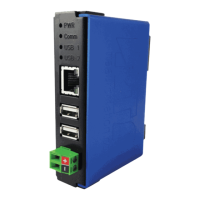
- LED Indicators: The gateway is equipped with LEDs (PWR, Comm, USB 1, USB 2) that provide visual feedback on its operational status.
- PWR LED: Solid green indicates power is supplied; off indicates no power.
- Comm LED: Solid green indicates connected and communicating; blink green indicates startup; blink red (slow) indicates no longer has a good connection to the PLC; blink red (fast) indicates configuration has changed and a reboot is necessary; off indicates the Ethernet cable is unplugged.
- USB 1 & USB 2 LEDs: Solid green indicates a valid USB device is connected; alternate blink green fast (5Hz) indicates a communication failure; alternate blink green (1Hz) indicates a fatal USB initialization error; off indicates no USB device detected. For printer-specific behavior, blink green (2Hz) indicates out of paper, and repeating 2 blink green for 1 second indicates a paper jam or out of ink.
- Revision Listing: Displays the full catalog number of the gateway, which is useful when contacting RTA Technical Support.
- Diagnostics Logging: Allows for logging diagnostic information, which can be helpful for advanced troubleshooting.