28 Installation MCE-325 Programmable User Station
Bosch Security Systems, Inc.
Technical Manual
F.01U.193.228
Rev. 13
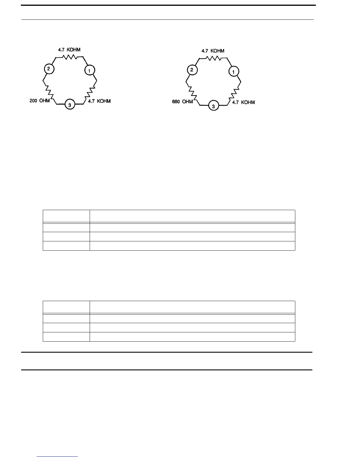
4-wire Termination
When 4-wire outputs are used, termination resistors must be installed for proper operation. The output amplifiers are current
sources, and the output level is determined by the terminating resistor values. These resistors would normally be installed in
the cable connector, but may be placed at any point in the signal path. Recommended values are shown in Figure 15.
Program Inputs, J14 and J15
The PROGRAM A and B inputs accept line-level (0dBu nominal), balanced audio. The program inputs are connected using
¼- inch stereo phone plugs.
External Speaker, J27
The SPEAKER OUTPUT jack provides a bridging-type output for an external speaker (8Ω minimum). The external speaker is
connected using a ¼-inch phone plug.
CAUTION: Do not let either speaker lead contact ground. The MCE-325 provides a bridging-type speaker output. The
external speaker is turned on and off by the front panel SPKR ON switch.
FIGURE 15. 4-wire Output Terminations
TABLE 6. Connectors J14 and J15
Section Function
Tip Program High
Ring Program Low
Sleeve Common
TABLE 7. Connector J27
Section Function
Tip Speaker plus
Ring Speaker minus
Sleeve No connection
 Loading...