PortaMonitor Getting started Page 6-3
6.4. Conneting the PortaMonitor 1064V5
The PortaMonitor 1064V5 features two digital inputs and a power
supply connector. The pinning is as follows:
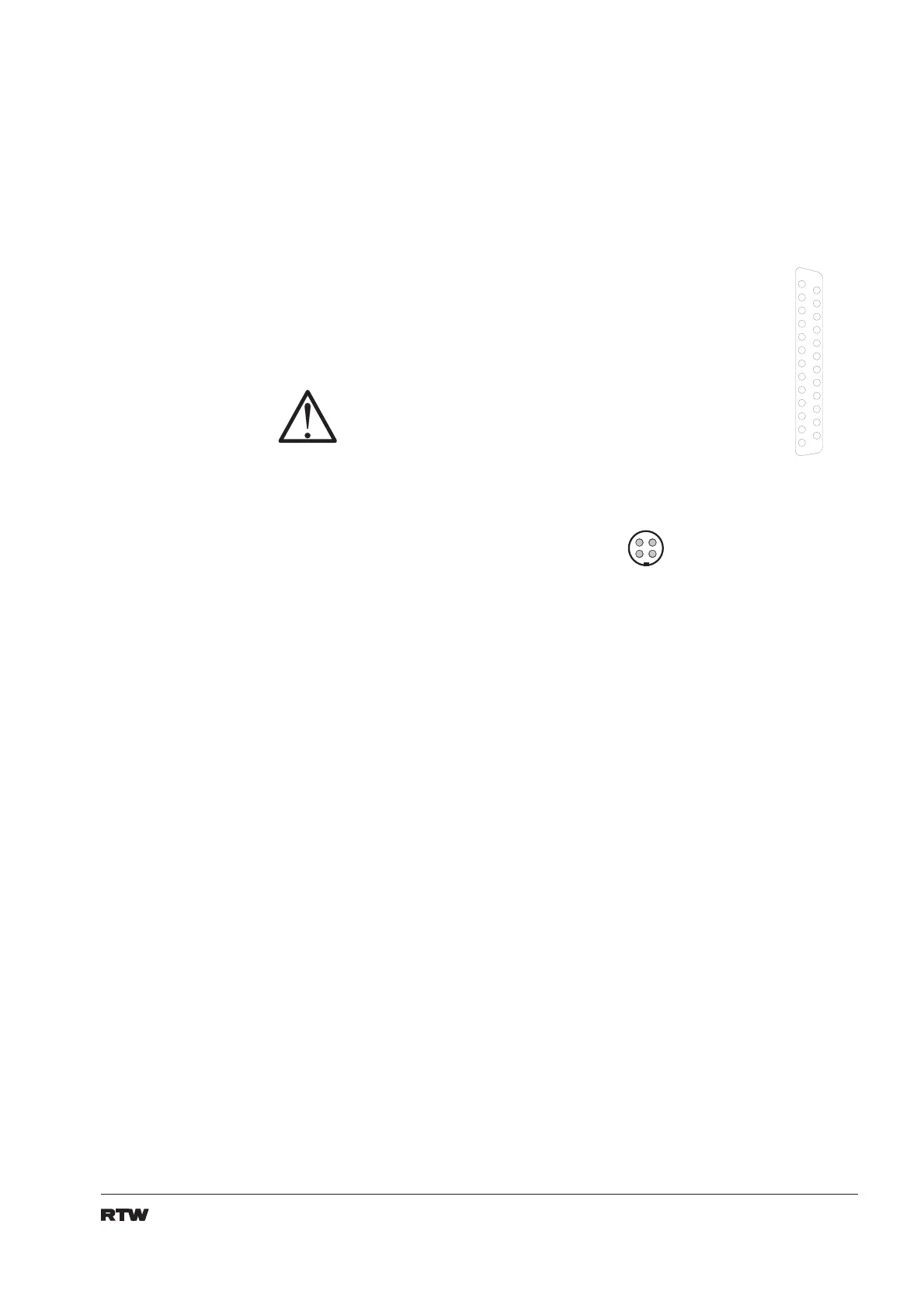
Sub-D-25-pin.:
Pin: Function:
18 audio input digital (AES/EBU) 1 (+, hot)
6 audio input digital (AES/EBU) 1 (-, cold)
19 screen/case
4 audio input digital (AES/EBU) 2 (+, hot)
17 audio input digital (AES/EBU) 2 (-, cold)
5 screen/case
1 +5 V DC (must be stabilized)
14 +5 V DC (must be stabilized)
20 V
Power supply connector:
Pin: Function:
1-2 +5 V DC (must be stabilized)
3-4 0 V
P i n 1
P i n 2
P i n 3
P i n 4
P i n 5
P i n 6
P i n 7
P i n 8
P i n 9
P i n 1 0
P i n 1 1
P i n 1 2
P i n 1 3
P i n 1 4
P i n 1 5
P i n 1 6
P i n 1 7
P i n 1 8
P i n 1 9
P i n 2 0
P i n 2 1
P i n 2 2
P i n 2 3
P i n 2 4
P i n 2 5
3 1
4 2
DC supply via multi-
core should be a
special exception.
The power supply and
the 25-pin sub-D
connector are wired
in parallel. The use of
a second supply or
shorting the corres-
ponding lines is
inadmissible.
The PortaMonitor requires
AES/EBU signal present at
digital input 1 for digital ope-
ration. The internal master-
clock will be devided from
this signal. Digital input
signals for input 2 must be
in sync to input 1.
 Loading...