EasyManuals Logo
Home>RuggedCom>Network Router>RUGGEDSWITCH RS900G

RuggedCom RUGGEDSWITCH RS900G Installation Guide

RuggedCom RUGGEDSWITCH RS900G
20 pages
To Next Page IconTo Next Page
To Previous Page IconTo Previous Page
Page #13 background imageLoading...
Page #13 background image
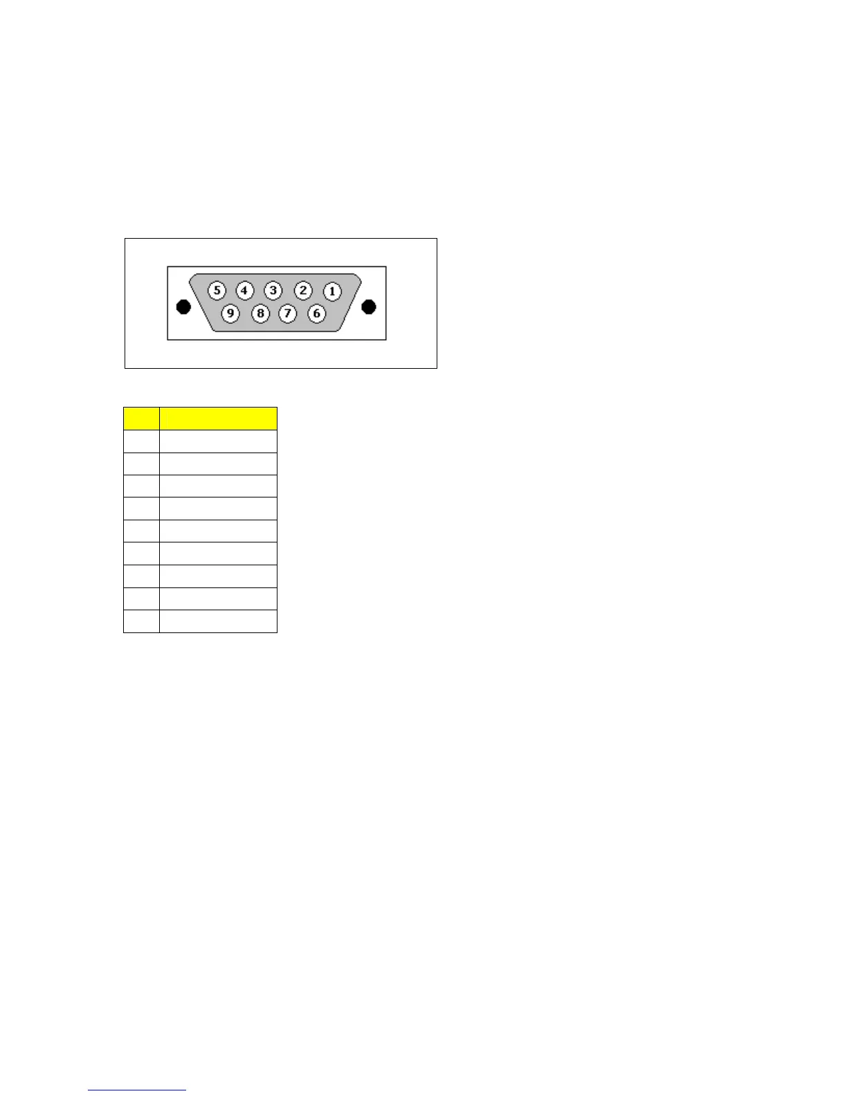
2.5 RS232 Port Wiring
The RS232 port is used for configuring the unit. A straight-through serial cable with a DB-9
connector is required. There is no need to crossover the Transmit and Receive signals from the PC
side since this has been done internally as shown in the figure below.
Fig 2.5.1 RS232 Female DCE pin-out
Pin Signal
1 No Connection
2 Transmit Data
3 Receive Data
4 No Connection
5 Ground
6 No Connection
7 No Connection
8 No Connection
9 No Connection
Table 2.5.1 RS232 Female DCE pin-out
NOTE: This port is not intended to be a permanent connection and the cable shall be less than 2m
(6.5 ft) in length.
13
2010 RuggedCom Inc. All rights reserved Rev105

Other manuals for RuggedCom RUGGEDSWITCH RS900G

Questions and Answers:

Question and Answer IconNeed help?

Do you have a question about the RuggedCom RUGGEDSWITCH RS900G and is the answer not in the manual?

RuggedCom RUGGEDSWITCH RS900G Specifications

General IconGeneral
BrandRuggedCom
ModelRUGGEDSWITCH RS900G
CategoryNetwork Router
LanguageEnglish

Related product manuals