Do you have a question about the RuiDa RDC6442G-DFM-RD and is the answer not in the manual?
Product certified by CE (Commutate European) safety standards.
Product certified by EU legislation for hazardous substances (ROHS).
Product certified by Federal Communications Commission (FCC) for safety.
Explains symbols for Dangerous, Warning, Cautious, Important information, and Laser radiation.
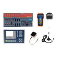
Overview of the RDC644XG system for laser engraving and cutting.
Details the different versions and features of the RDC644XG controller models.
Compares performance features of RDC644XG against other RDLC models.
Provides millimeter dimensions for the MainBoard mounting.
Provides millimeter dimensions for the control panel.
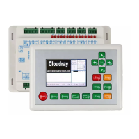
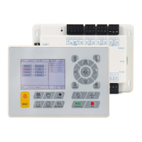
Visual representation of the MainBoard with connector and component labels.
Visual representation of the control panel buttons and their functions.
Illustrates the wiring for connecting components to the control system.
Lists and explains the purpose of each LED indicator on the system.
Details interfaces for power source and control panel connection.
Explains interfaces for Udisk, PC, and Ethernet communication.
Defines pin functions for general output (CN1) and input (CN2) ports.
Details interfaces for motor drivers and laser power control.
Introduces the system's two independent digital laser power control interfaces.
Illustrates the wiring example for a glass tube laser power supply.
Illustrates the wiring example for an RF-laser power supply.
Explains the light-coupled isolation technology for motor driver input signals.
Provides diagrams showing how to connect motor drivers to the controller.
Shows input connection examples, specifying logic levels for water protection and other inputs.
Illustrates output connection examples for driving relays, LEDs, and buzzers.
Overview of the control panel layout and explanation of individual keys.
Describes the system's main interface screen and its components.
Explains the various functions accessible via the Z/U key.
Guides on using memory and U disk files for loading, saving, and managing jobs.
Provides information on common alarm messages and how to respond to them.
Details factory-set parameters for motor control, laser configuration, and machine settings.
Explains user-configurable parameters for cutting, scanning, feeding, and reset operations.
| Brand | RuiDa |
|---|---|
| Model | RDC6442G-DFM-RD |
| Category | Control Systems |
| Language | English |