Do you have a question about the RuiDa KT332N and is the answer not in the manual?
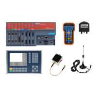
Overview of the KT332N control system, its features, and capabilities.
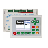
Detailed measurements and specifications for the main controller unit.
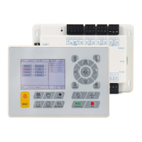
Detailed measurements and specifications for the HMI control panel.
Visual and functional overview of the KT332N controller unit.
Visual overview of the HMI control panel and its layout.
Schematic illustrating the electrical connections for the control system.
Details on the main power input for the controller and its requirements.
Specifications for general and dedicated input/output signal ports.
Configuration and wiring for laser power control interfaces.
Wiring diagram for connecting glass tube laser power supplies.
Wiring diagram for connecting RF CO2 laser power supplies.
Explanation of common anode connection methods for stepper drivers.
Schematic illustrating wiring connections for stepper motor drivers.
Wiring examples for various input ports on the controller.
Wiring examples for output ports and their applications.
Introduction to the HMI panel and its key characteristics.
Detailed explanation of the main operational interface display.
How to adjust speed and power parameters via the HMI.
Guide to accessing and modifying various system parameters through the menu.
Detailed explanation of vendor-configurable motor control parameters.
Explanation of user-adjustable parameters affecting cutting performance.
| Model | KT332N |
|---|---|
| Max Output Current | 3A |
| Touch Screen | No |
| Operating Temperature | 0-50°C |
| Axes | 3 |
| Input Voltage | 24V |
| Communication Interface | USB |
| Compatible Software | RDWorks |
| Supported File Formats | AI, DXF, PLT, BMP |
| CPU | ARM |
| RAM | Unknown |
| Flash Memory | Unknown |
| Communication Ports | USB |
| Expansion Slots | Unknown |
| Power Supply | External |
| Weight | Unknown |
| Protection Rating | Unknown |
| Display | 3.5 inch TFT LCD |