Hardware Installation and Reference Guide Product Installation
Adopt the solid state connection mode for the power cable adapter to avoid tension.
Conduct cabling management in hidden positions in a neat and artistic way, and apply protective cover over the
cables.
Improper connection of the ACC may lead to a risk of losing system files.
Adapter (Available for tests only)
Select an adapter with a voltage within the required range. Specific requirements are as follows:
Input voltage: 100–240 V AC; input current: ≥ 1 A
Output voltage: 9–36 V DC; output current: ≥ 2 A
2.2.4 Power-On and Begin To Use
Power supply and antenna verification
Check whether the power cable on the rear panel is properly connected.
Check whether the antennas are properly connected.
Power-off
Power off RG-MTFi-M520 before maintenance to avoid damage to the SIM card, the hard disk, and the radio frequency
(RF) module.
After RG-MTFi-M520 is powered on, if PWR is steady on green, it indicates that RG-MTFi-M520 runs properly. If the
indicator 3G/4G starts blinking, it indicates that a 3G/4G network is connected. If the indicator WiFi starts blinking, it
indicates that WiFi is enabled.
A debugging test can be performed after RG-MTFi-M520 is started, or debugging can be completed before
RG-MTFi-M520 is installed on the vehicle. Connect RG-MTFi-M520 to the network using SSID to check whether
RG-MTFi-M520 can access the network properly.
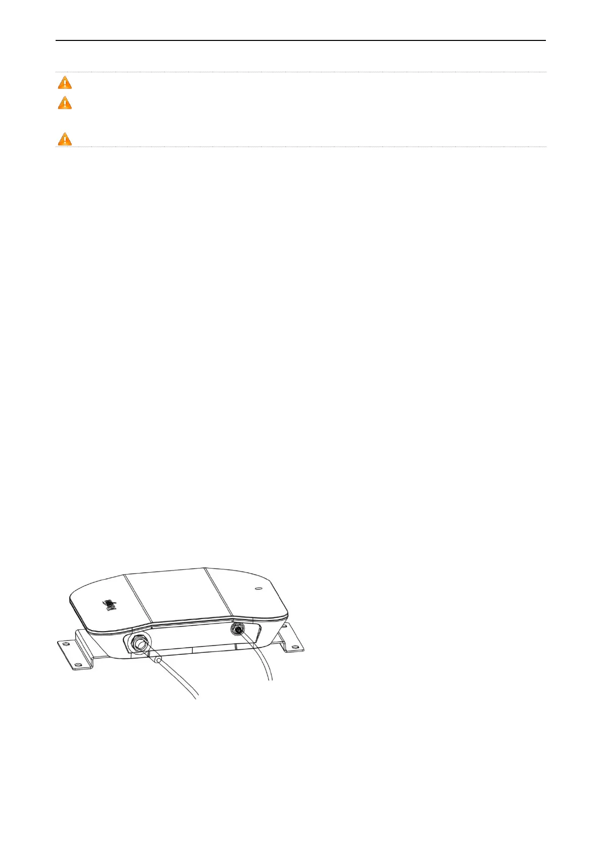
The following figure shows installation of the power cable and antenna.
Figure 2-5 Single Module and External GPS Antenna
Figure 2-6 Single 3G/4G Module and Six External Antennas
 Loading...