7
Installation:
Push tabs on either side of the pump to remove pump from the base.
Werecommendusing#8stainlesssteelatheadscrewsofanadequatelengthas
tosecurethepumpbutnotpenetratetheentirethicknessofthehull.Useaexible
sealant in the screw holes to prevent water from penetrating the screw holes.
Insert the pump into the base and push down until an audible
“click” is heard.
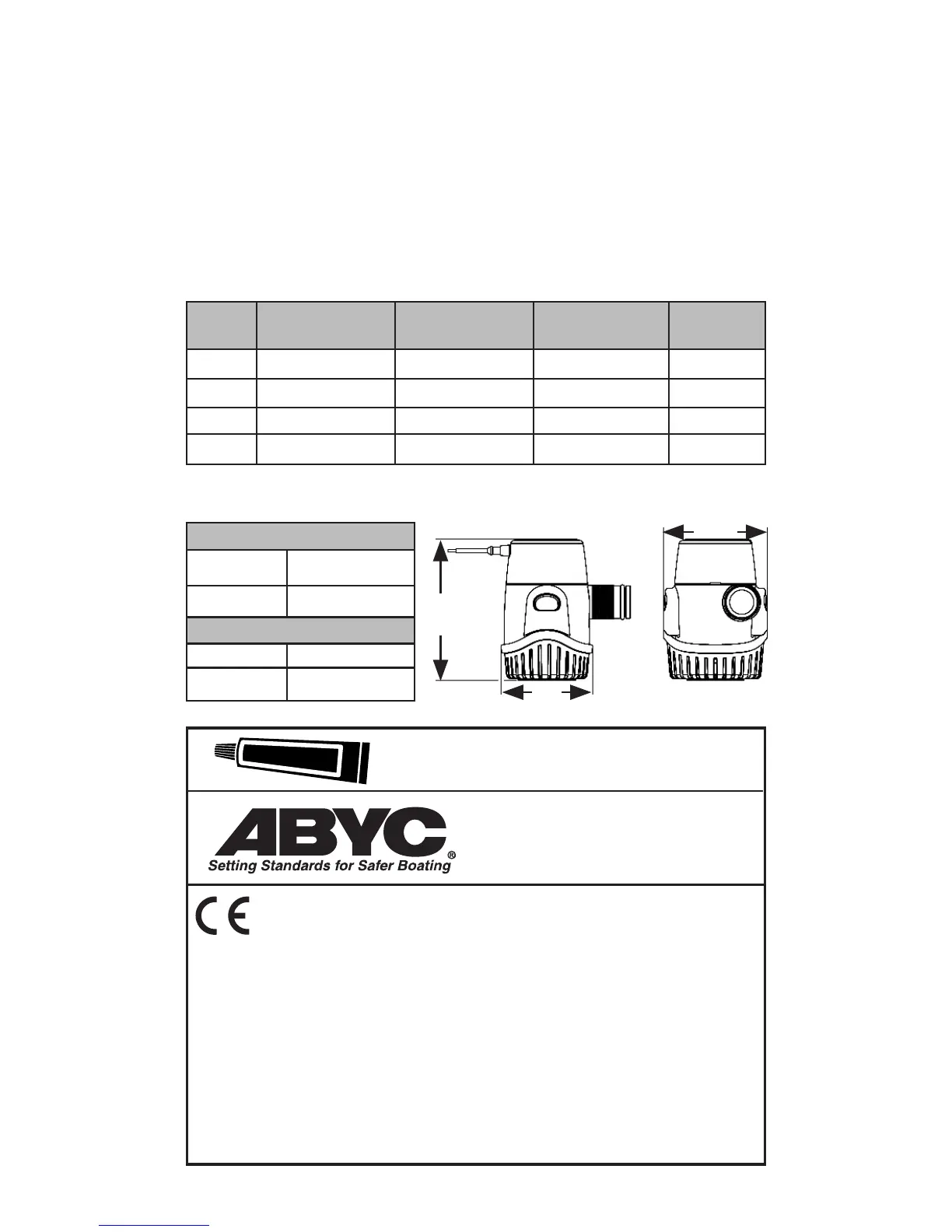
GPH
Series
@ Oft
Om -0 kPa
@ 3.3 ft
1 m -10 kPa
@ 6.7 ft.
2m-20 kPa
Max Head
Height
360 417.3 (1579) 308 (1165) 150 (567.81) 12’(3.7m)
500 572 (2165.2) 470 (1779.1) 270 (1022.1) 11’(3.4m)
800 1045 (3955) 790 (2990.5) 575 (2175) 12’(3.7m)
1100 1116 (4224) 1005 (3804.3) 825 (3123) 10’(3m)
Flow - GPH (LPH)
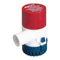
Height
Standard Pumps
360/500 3.9”(10cm)
800/1100 4.4”(11.2cm)
Electronic Sensing
360/500 4.2”(10.7cm)
800/1100 4.7”(12cm)
We hereby declare, under our sole responsibility, that our product
to which this declaration relates has been designed to comply in
accordance with the following Directives:
Electromagnetic Compatibility Directive 2014/30/EU
Recreational Craft Directive 2013/53/EU
RoHS 2011/65/EU.
With the relevant selections of the following Standards:
ISO 8846: (EN 28846): Ignition Protection
ISO/EN 8849: Electrically Operated DC Bilge Pumps
ISO 10133:2012 / Extra Low Voltage D.C. Installations
ISO 15083:2003 / Bilge Pumping Systems
All mounting holes must be sealed with a
marine grade sealant to prevent water intrusion.
Install to ABYC
H-22 and E-11
See Height
Chart
2.5”
(6.4cm)
2.9”
7.4cm)