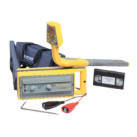
Ground Return Probe Insertion
Circuitry between the ground spikes provides a path for current in the soil returning to the GROUND ROD.
The current enters one spike of the GROUND RETURN PROBE and exits the other spike. The GRP should be
inserted into the soil with consistent force and depth.
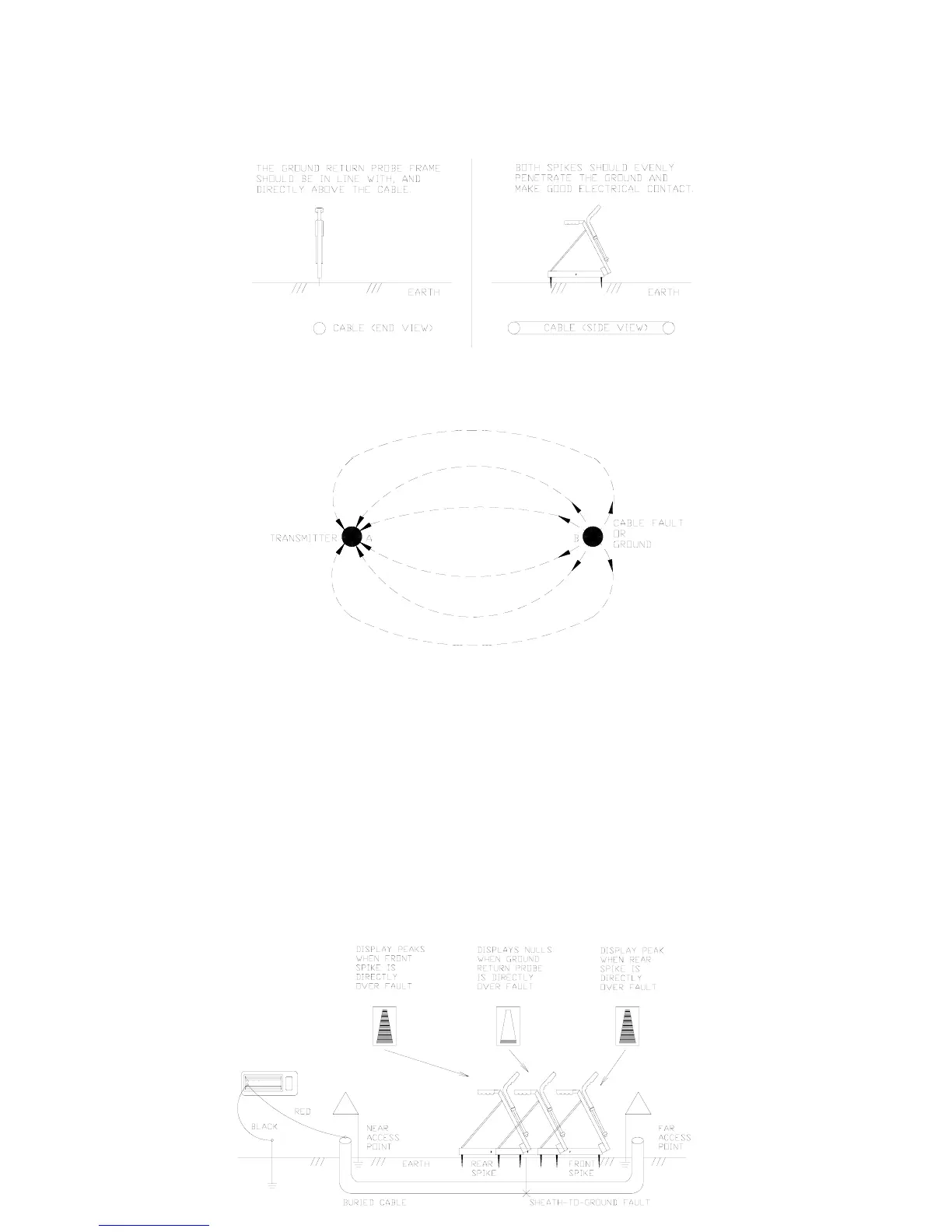
The current in the soil spreads out from the fault like the spokes of a wheel. The current is highly concen-
trated in the soil near the fault as it begins its return, and near the G
ROUND ROD as it finishes its return.
Notice that the current is widely dispersed in the soil between the fault and the G
ROUND ROD.
As you walk the path using the GRP, drop the probe every three or four steps. As you near an area of high
current concentration in the soil, the G
ROUND ROD or the fault, the RECEIVER will record higher and higher
readings. You will find it necessary to reduce the R
ECEIVER’S sensitivity by pressing the GAIN CONTROL
button. Once the signal starts to increase, you should slow down and take smaller steps, covering smaller
segments of ground to avoid passing the fault.
The R
ECEIVER will continue to record higher current readings until one spike of the GROUND RETURN PROBE
passes the fault. When one spike of the GRP is on each side of the fault, the currents will subtract and pro-
duce a NULL. To record the deepest NULL, press the GAIN CONTROL button to keep the NULL on the
meter scale and move the GRP an inch at a time until the deepest NULL is recorded. The fault lies in the
center of the GROUND RETURN PROBE spikes.
Ground Return Probe Fault Locating
16