18 - English
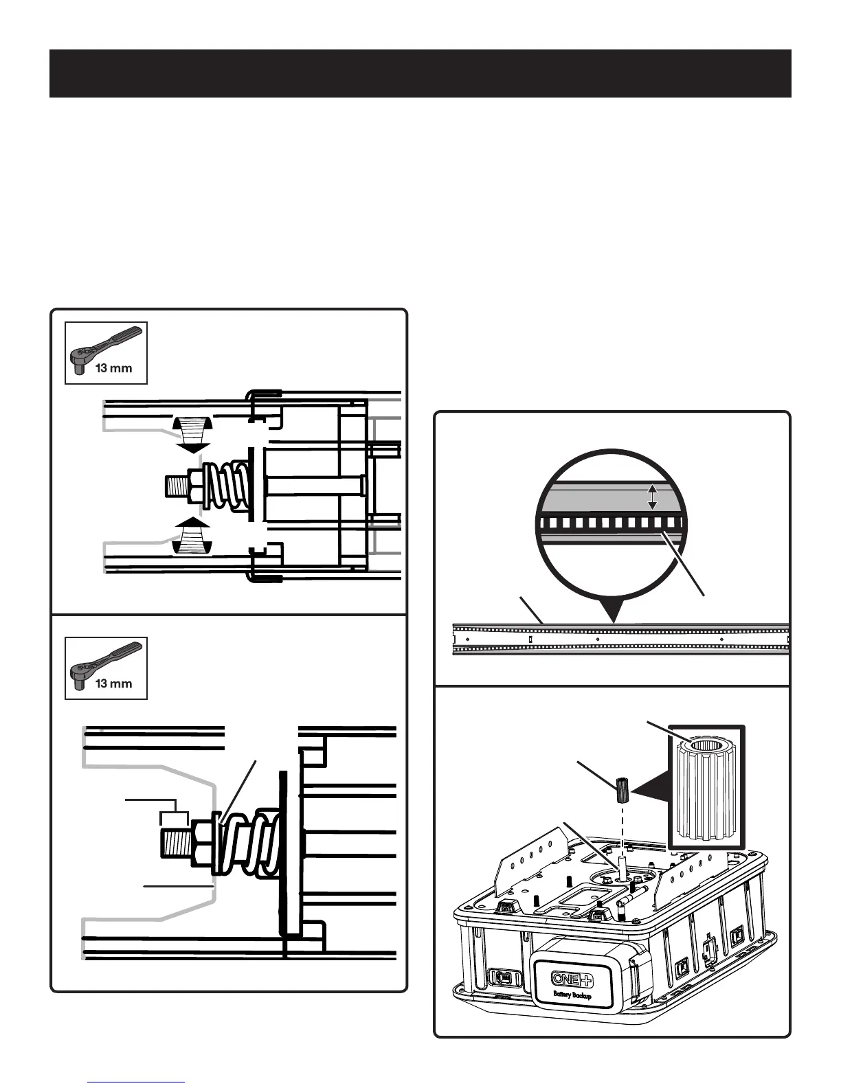
Fig. 20
Fig. 19
Tighten
Loosen
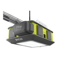
3/8 in. to
1/2 in.
Base of
the nut
Edge of
the brace
Rail
Edge
CENTER OF RAIL ASSEMBLY
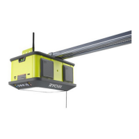
ATTACHING RAIL ASSEMBLY TO POWER
HEAD
See Figures 22 - 25.
Locate the following items:
Power Head
Bracket (2)
Nut (M6) [4]
Sprocket
Rail Assembly
Place the power head on a towel or the packaging material
with the light cover facing down.
Remove the tape securing the Wi-Fi antenna and raise it
to an upright position to ensure the best Wi-Fi signal.
Place the sprocket onto the motor shaft with the round
side of the sprocket facing up.
Fig. 21
Fig. 22
Belt
1/8 in.
Gap
Sprocket
Round
Side
Shaft
ADJUSTING THE BELT TENSION
See Figures 18 - 21.
Using a 13 mm socket, turn the tension nut clockwise
to tighten the belt and counter-clockwise to loosen it.
Adjust the nut until there is approximately 3/8 to 1/2 in.
of exposed thread showing above it or until the base of
the nut is aligned with the edge of the brace.
When properly tensioned, there should be about a
1/8 in. gap between the belt and the edges of the
intermediate rail near the center of the rail assembly.
ASSEMBLY