Page 10
ADJUSTMENTS
INSTALLING/REMOVING CUTTERS WITH
A 1/4 in. (6.4 mm) DIAMETER SHANK
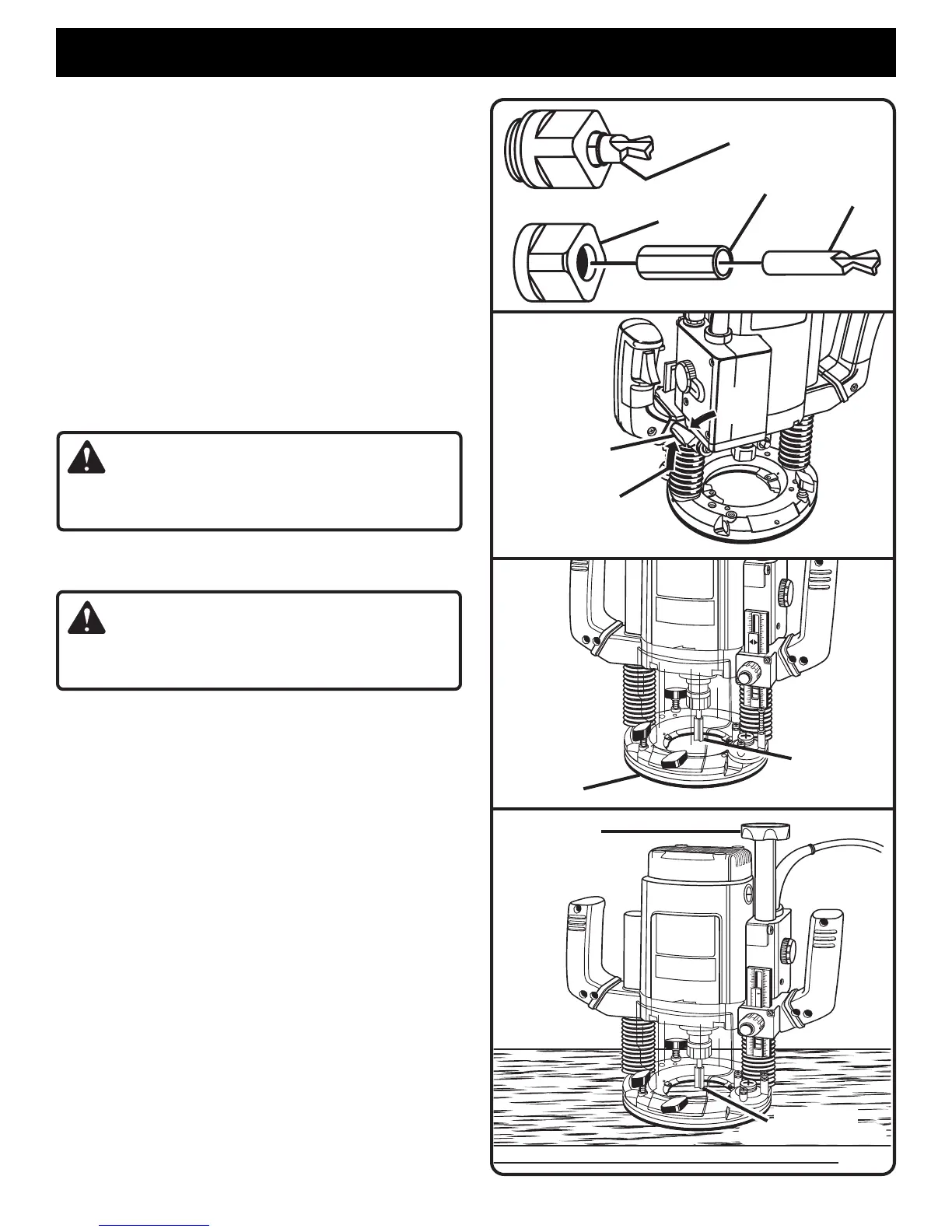
As mentioned previously, a 1/4 in. (6.4 mm) bit adapter has
also been provided with your router so that cutters with 1/4
in. (6.4 mm) shank bits can be used.
See Figure 4.
■ If using a cutter with a 1/4 in. (6.4 mm) diameter shank,
follow the instructions on the previous page to loosen
the collet nut and remove any 1/2 in. (13 mm) diameter
shank cutters from the collet.
■ Place the 1/4 in. (6.4 mm) bit adapter provided in the
collet.
See Figure 4.
■ Insert shank of cutter into collet until shank bottoms out,
then pull it out 1/16 in. (1.6 mm) to allow for expansion
when the bit gets hot.
■ Tighten the collet nut securely by turning clockwise with
the wrench provided.
See Figure 3.
WARNING:
If collet nut is not tightened securely, cutter may come out
during use causing serious personal injury.
TO SET DEPTH OF CUT
■ Unplug your router.
WARNING:
Failure to unplug your router could result in accidental
starting causing serious injury.
■ Raise the cutter by releasing the plunge lock and re-
lease lever.
See Figure 5.
■ Adjust depth control knob until cutter is inside router
subbase
. See Figure 6.
■ Place your router on a flat surface
.
■ Lower router until tip of cutter barely touches the
workpiece
. See Figure 7.
■ Tighten the plunge lock and release lever to lock cutter
at "zero" depth of cut. NOTE: If desired, adjust the depth
control knob until it seats against the router housing
.
This will provide a positive stop at "zero" depth of cut.
■ Rotate depth stop to desired position, loosen lock knob,
then turn adjustment knob until stop bar touches stop
screw on depth stop
. See Figure 8.
■ Pick a reference point on the scale
.
■ Next, turn adjustment knob in the opposite direction,
lifting stop bar to obtain desired depth of cut.
See
Figure 8.
For example, if setting 1/16 in. (1.6 mm)
depth of cut, the scale will move 1/16 in. (1.6 mm)
from the reference point.
■ Tighten lock knob securely
.
■ Position your router so that the cutter can extend below
the subbase for desired depth setting.
See Figure 9.
CUTTER WITH 1/4 in. (6.4 mm)
SHANK DIAMETER
CUTTER
1/2 IN. (13 mm)
COLLET NUT
1/4 IN. (6.4 mm)
BIT ADAPTER
Fig. 4
Fig. 6
CUTTER
INSIDE SUBBASE
SUBBASE
DEPTH
CONTROL KNOB
Fig. 5
in
m
m
0
1
2
3
4
1
2
3
9
3
1
Fig. 7
CUTTER AT
ZERO DEPTH OF CUT
A
B
C
D
E
F
TO
LOCK
TO
UNLOCK
PLUNGE
LOCK AND
RELEASE LEVER


 To Next Page