Do you have a question about the SAB Heli Division GOBLIN KRAKEN NITRO 580 and is the answer not in the manual?
| Category | Toy |
|---|---|
| Brand | SAB Heli Division |
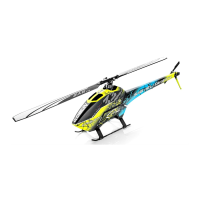
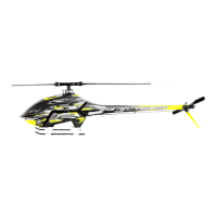
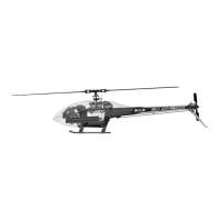
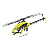
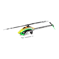
| Model | GOBLIN KRAKEN NITRO 580 |
| Type | RC Helicopter |
| Engine | Nitro Engine |
| Skill Level | Advanced |
| Assembly Required | Yes |
| Tail Rotor Diameter | 260mm (with 95mm tail blades) |
Read manual, register kit online for updates and important developments.
Detailed technical specifications including weight, dimensions, and component sizes.
Key warnings and considerations for operating the helicopter safely and responsibly.
Instructions for safe flying practices and operational areas.
Disclaimers regarding manufacturer liability for product damage or loss.
Details of the warranty coverage and limitations for the product.
List of external components and systems needed for assembly.
Required tools, lubricants, and adhesives for building the helicopter.
General assembly advice, including thread lockers and symbols.
Assembly steps for the helicopter's clutch unit components.
Procedure for assembling the engine mount and supports.
Information on available gear ratios for optimal head speed.
Methods for installing the RPM sensor on the engine.
Assembly instructions for the left fan case.
Assembly instructions for the right fan case.
Steps for assembling the linkage components for the engine unit.
Instructions for assembling the fuel tank and its lines.
Instructions for assembling and verifying the transmission unit.
Information on using standard size servos, not included in the kit.
Steps for assembling and mounting the servos for the swashplate.
Assembly of the uniball radius arm components.
Assembly of the radius arm parts.
Assembly of the linkage rods.
Assembly of the center hub.
Guide to setting up O-rings for different flight styles.
Steps for assembling the tail rotor components.
Assembly of the tail boom group components.
Instructions for installing and connecting the tail servo.
Assembly of the swashplate and related components.
Assembly of the linkage rods connecting servos to the swashplate.
Procedure for correctly tensioning the tail drive belt using the 'zig-zag' method.
Assembly of the X-ross plate and mounts.
Steps for installing the Flybarless (FBL) system support.
Using rubber dampeners to reduce vibrations for FBL system.
Installation of additional support structures for the FBL/RX system.
Instructions for installing the helicopter canopy and quick knobs.
Pre-flight checks and setup procedures for safe operation.
Details on the HPS head and its dampening setup options.
Recommendations for tail rotor setup and performance tuning.
Routine checks, lubrication, and part replacement for upkeep.
Ensure consistent dampening on both main and tail rotors.
Ensure main blades are securely tightened before each flight.
Verify tightness of main hub screws for structural integrity.
Confirm the fuel line connection is secure and leak-free.
Ensure proper tension on the tail and motor belts.
Verify tightness of tail group screws for secure assembly.
Inspect main and servo linkages for smooth operation and security.
Verify tail pulley set screw tightness, recommending green Loctite.
Confirm FBL/RX connectors are secure, with hot glue recommended.
Ensure smooth bell crank movement and secure screw tightening.
Lubricate key components like main shaft, tail slider, bearings, and ball connections.
Overview of the pre-assembled and verified transmission module.
Procedure for replacing the main shaft of the transmission module.