SABAF S.p.A.
Via dei Carpini, 1
25035 Ospitaletto (Brescia) Italia
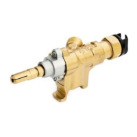
Model 10, 10P, 10X, 10Y, 10PZ
hot plates, ovens, grills etc
minimum working temperature
maximum working temperature
nominal flow rate
(except inlet variants 15-16)
0.361 m
3
/h (test gas: air - pressure drop 125 Pa – AS 4624-2005)
0.323 m
3
/h (test gas: air - pressure drop 100 Pa – EN 126-2012)
Reduced flow rate
(except inlet variants 15-16)
0.067 m
3
/h (test gas: air - pressure drop 125 Pa – AS 4624-2005)
0.060 m
3
/h (test gas: air - pressure drop 100 Pa – EN 126-2012)
nominal flow rate
(inlet variants 15-16)
0.146 m
3
/h (test gas: air - pressure drop 125 Pa – AS 4624-2005)
0.130 m
3
/h (test gas: air - pressure drop 100 Pa – EN 126-2012)
Reduced flow rate
(inlet variants 15-16)
0.045 m3/h (test gas: air – pressure drop 125 Pa – AS 4624-2005)
0.040 m3/h (test gas: air – pressure drop 100 Pa – EN 126-2012)
opening angle of max. flow rate
opening angle of min. flow rate
160° (models 10; 10X) – 210° (models 10P; 10PZ)
leakage 60 cc/h (1 ml/min) (air - pressure 15 kPa)
leakage 20 cc/h (0.3 ml/min) (air - pressure 15 kPa)
gas valve continued operation
40,000 cycles (EN 126:2012 - EN 13611:2007 + A2:2011)
10,000 cycles (AS 4624 – 2005)
Flame supervisor device continued
operation
10,000 cycles (EN 126:2012 - EN 13611:2007 + A2:2011)
2,000 cycles (AS 4624 – 2005)
bracket, flange (see inlet variant table)
storage temperature range
hold-on current/drop-out current
(safety device)
< 180 mA / > 60 mA (version 1)
< 110 mA / > 20 mA (version 2)
< 60 mA / > 10 mA (version 3)
Themocouples maximum closing
time
These valves can be used with pipes of various diameters and flat manifolds.
To ensure a perfect seal, place an elastomer gasket between the manifold and the valve.
Gaskets of different materials can be used for the manifold depending on the temperature reached: silicon
elastomer gaskets are resistant up to 130°C (all colors except black) while nitrile elastomer gaskets are
resistant up to 80°C (black gasket).
INSTRUCTIONS FOR USE
To turn the valve on, simultaneously press and turn the control shaft.
Holding down the control shaft and turning it anti-clockwise allows the gas to pass to the burner.
A few seconds after the burner ignites, the thermocouple generates enough current to hold the safety
magnet open. The control shaft needs no longer be pressed down.
When it's indicated on the assembly drawing the ignition of the valve can only be done with the spindle in
90°A position.
Maximum flow-rate is reached after turning the control shaft through 90°; reduced flow-rate is reached by
continuing the rotation up to 160° except model 10Y (210° for model 10P and PZ).
 Loading...