SABAF S.p.A.
Via dei Carpini, 1
25035 Ospitaletto (Brescia) Italia
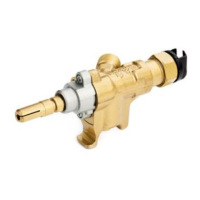
Model 10, 10P, 10X, 10Y, 10PZ
The gas valve can be equipped with one or more microswitches, which can be firmly fastened by means of a
metal staff. The microswitches are activated by simply pushing the spindle inward or by rotation of the
spindle – see table 1.
As regards the gas valve model 10, X variant (cap marked X), the control shaft can be also turned 90°
clockwise, without any passing of gas, to operate one or more microswitches.
As regards the gas valve model 10, Y variant (cap marked Y), the maximum rotation is 90° anti-clockwise, in
this position the maximum flow-rate is reached.
If the flame should accidentally go out, the thermocouple cools and the current is reduced, the safety magnet
is closed and the flow of gas is blocked after a few seconds.
The valve has an adjustable perforated metering screw (by-pass) which fixes the reduced flow-rate at a
preset value when fully tightened. If a different type of gas is used, the amount of reduced flow can be
adjusted by turning the by-pass beside the cap with a screwdriver.
TABLE 1 - MICROSWITCH CHARACTERISTICS
Max. operating temperature
ASSEMBLY INSTRUCTIONS
The valves are designed to be used inside the cooking appliances, protected from any possible
infiltrations of liquid or dirt and from the atmospheric agents. The non-observance of this
prescription can compromise the correct working and the safety of the product.
The valves are designed to be used with manifolds of different diameters using flange or bracket fastenings.
To ensure a perfect seal, place an elastomer gasket between the ramp and the valve.
The outlet is designed for an injector or connection pipe to the burner.
To avoid damage that may compromise correct functioning of the valve, do not exceed the tightening torques
listed in the attached tables.
To avoid dirt or other material entering the equipment which may affect functioning of the valve, a
suitable filter should be mounted on the manifold supply inlet.
MAINTENANCE INSTRUCTIONS
Maintenance of the taps is not foreseen, in case of failure or incorrect operation replace the tap with a new
one (same model and same characteristics).
NB.: Leak test should be performed using a suitable appliance. Leak test mustn’t be done by means
of a flame or immersion of the valve in water or other liquids. The non-observance of this
prescription can compromise the correct working and the safety of the product.
 Loading...