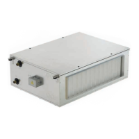
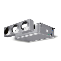
The Ocean ECM is a series of double-insulated panel fan coils designed and constructed for ventilating, heating, cooling, and air conditioning various industrial, commercial, sports, and civil environments. These units are available in two main versions: Compact and Modular. Both versions are built with self-extinguishing sandwich panels for thermo-acoustic insulation.
Function Description
The primary function of the Ocean ECM units is to provide climate control (heating, cooling, and ventilation) for indoor spaces. They are designed for use in two-pipe or four-pipe systems, depending on the specific model and coil configuration. Certain models also include germicidal lamps for air purification and humidification sections for maintaining desired humidity levels.
Important Technical Specifications
The core components of both Compact and Modular versions are identical and include:
- Fan Assembly: This group consists of a three-phase permanent magnet DC brushless electronic motor, controlled by current reconstructed according to a BLAC sinusoidal wave. The inverter board, powered by 230V single-phase (50-60 Hz), generates a frequency-modulated, waveform power supply. The fan assembly also includes two plastic impellers, dynamically balanced and directly coupled to the motor shaft. The casing is a self-supporting sandwich panel made of two galvanized sheet metal panels (inner galvanized, outer pre-painted RAL 9006), with a 22 mm thick, 30 kg/m³ density polystyrene foam panel in between. Electrical connections are made via a terminal board. The motor is designed to operate in an air temperature range of -10°C to +55°C. It is crucial to ensure sufficient pressure losses in the circuit for the fan to operate within optimal curves and to prevent current/power absorption from exceeding the maximum values specified in the manual (e.g., for 230V 50-60Hz, motor absorption ranges from 186W to 1045W, and current absorbed from 1.3A to 4.7A, depending on the model).
- Heat Exchange Coils: These coils are constructed with copper tubes and aluminum fins, mechanically bonded by an expansion process. For two-pipe systems, coils are available in 3, 4, or 6 rows. For four-pipe systems, additional coils are available in 1, 2, or 3 rows. Coil supply connections are male gas threaded, with dimensions ranging from 3/4" to 1 1/4" depending on the model.
- Filter Group: The filter unit can be equipped with a G0 regenerable synthetic filter or a Class ePM10 50% (ex G4) synthetic filter. An optional Class ePM1 55% (ex F7) filter is also available as an accessory (delivered unassembled). Filter dimensions vary by model (e.g., for G0 filters, models 1-2 have A=1165mm, B=150mm, C=325mm; for ePM10 50% - G4 filters, models 1-2 have A=1165mm, B=150mm, C=325mm, with a weight of 8.4kg without packaging and 9.1kg with packaging).
- Germicidal Lamp Section (SLG): This optional section contains a UV-C lamp. Models 1-3 have a 78W lamp, while models 4-5 have a 105W lamp. The lamp is protected by Uvlon Pipe sheathing, providing IP44 rating and containing glass fragments in case of breakage. It includes a power supply unit and a microswitch on the lower inspection panel to cut power if the panel is improperly opened.
- Humidification Section (SUD-DP/SUD-V): The SUD-DP is an evaporative wet pad system, supplied with water from the waterworks. It requires an installer-provided solenoid valve (controlled by a humidistat) and a manual calibration valve to regulate water flow. Excessive flow can cause water to leak from the drip tray. The SUD-V is a steam humidification accessory with a stainless steel steam wand, upper holes for steam outlet, condensation return, and a separate internal drip tray with drain. Steam flow rates range from 1.6 kg/h to 6.5 kg/h depending on the model.
- Electric Coil Section (SBEL): This section comprises electric resistances with a safety thermostat, housed in a galvanized and insulated steel casing. It is available in single-phase 230 Vac (for models 1-2) or three-phase 400 Vac (for models 1-5).
- Silencer Section (SXS): Designed to reduce noise levels.
- Plenum Section with Dampers (SPS): Available in various configurations (SPS-P-I, SPS-P, SPS-I) with different damper arrangements.
- Flanges (FMP/FRP, FMC/FRC): Used for connecting to ducts, available in flat rectangular or circular spigot designs.
- Air Grids (BMA-DP, GRA): Air outlet and intake grids.
- Interception Damper (SRA-DP): Used to control airflow.
Usage Features
The Ocean ECM units are controlled by electronic command panels. The manual references dedicated manuals for WM-AU, T-MB, and QCV control panels, which offer features such as:
- Manual or automatic 3-speed fan control.
- Thermostatic control of the fan or 1-2 valves.
- Manual or automatic seasonal changeover (summer/winter).
- Optional low-temperature cut-out thermostat (NTC probe).
- Weekly ON/OFF programming (for T-MB control).
For versions with electric heaters, thermostatic ON-OFF control of a cold water valve and the electric heating element is possible. The T2 Change-Over probe (optional) enables automatic heating/cooling changeover in two-pipe systems by sensing water temperature in the coil supply pipe.
Maintenance Features
Regular maintenance is crucial for optimal performance and longevity. Before any maintenance, disconnect the electrical power supply and hydraulic flow. Key maintenance tasks include:
- Air Filter: Access by removing the closing panel. Filters can be cleaned by shaking, aspiration against the airflow, or blowing with compressed air. Replace faulty or clogged filters as needed.
- Heat Exchange Coils: Periodically check for cleanliness (after initial start-up) and blow compressed air on the finned surface. Regularly discharge air from the pipes using the system's air discharge device. In winter, drain water from the coils if not in use. Ensure the condensate collection tray's siphon is always efficient.
- Humidifier: Gently brush the surface to remove limescale, which can obstruct cells and reduce efficiency or cause water leakage. Replace the evaporative wet pad if necessary.
- Annual Maintenance: General cleaning of all unit components, especially the condensate collection tray. Check motor power input and electrical connections. Inspect hydraulic connections. Refer to manual code 4051222 for a detailed maintenance plan.
Installation Guidelines
Mechanical installation must be performed by qualified personnel. The unit should always be installed with a slight slope (5mm) towards the condensate drain. The airflow direction indicated on the module label must be respected to avoid serious safety risks. Units are fixed to the ceiling using four perforated brackets and M8 threaded screws. Access panels should be provided in false ceilings for maintenance and filter removal.
For Modular versions, the fan unit, heat exchange coils, and filter must be assembled before installation. The correct sequence for horizontal compositions is filter section (air inlet), fan section, and battery section (air outlet). The SUD-DP humidification section must always be downstream of the SBC heating coil or SBEL electric coil. Vertical compositions do not allow SUD-DP or SBEL sections.
Hydraulic connections require using two spanners and insulating threaded ends to prevent leaks. A siphon trap must be connected to each condensate drain, with a slope of at least 3 cm/meter. Multiple drainage pipes should not flow into a single siphon trap. The height of the water column in the siphon must exceed the maximum unit pressure.
Electrical connections require an all-pole disconnection switch upstream with a contact separation suitable for overvoltage category III. Ensure proper earthing.
Safety Precautions
- Do not expose the appliance to flammable gases.
- Ensure the installation environment does not contain substances corrosive to aluminum fins.
- Provide a residual current device (RCD) with a nominal residual operating current not exceeding 30mA.
- Hot surfaces (water tubes up to 95°C, electric heating battery walls) should not be touched during operation.
- Wear protective gloves during maintenance.
- Do not insert objects or hands into the fan.
- Disconnect power before any intervention.
- Avoid loose clothing (ties, scarves) that could get caught in the fan section.
- Installation must be carried out by qualified technicians.
- Keep the work area clean.
- The germicidal lamp emits UV-C radiation, which can harm eyes and skin if exposed. Do not operate if the protective casing is damaged. The internal interlock switch for the UV-C lamp must not be bypassed.
Recycling and Disposal
Disposal of the product must comply with current environmental protection legislation and the European Directive 2012/19/UE (WEEE) for waste electrical and electronic equipment. Products should not be disposed of with normal solid urban waste; separate collection is mandatory, as indicated by the crossed-out wheeled bin symbol.