Engineering manual - SAB 193-233-283 S A-frame (including ATEX)
008831 en 2022.02
127/175
Installation instructions
9. Put the unitised flex disc between the hub and spacer until a bushing hole in the uni-
tised flex disc lines up with the bolt.
10. Slide the bolt through the bushing hole in the unitised flex disc.
11. Install the lock nut until it is snug.
Do not torque any lock nuts at this time.
12. The remaining bolts for this end of the coupling can be installed through the hub bolt
holes and flex disc bushing holes.
13. Install the unitised flex disc in the other end of the coupling. The unitised flex disc, as in-
stalled, should look flat and parallel with the mating hub and spacer flanges.
14. Torque the disc pack lock nuts as recommended in Table 46. Hold the bolts in place
while the lock nuts are torqued. Turning the bolts will damage the flex disc.
15. Centre the coupling between the shafts. Make sure that the keys are fully engaged in
their keyways.
The average gap dimension ‘G’ as shown in Fig. 83 at each disc pack should be within the val-
ue given in Table 46 +/-12.5% of the axial capacity of the coupling.
16. To improve the coupling installation and performance, it is recommended, if possible at
this stage, to rotate the assembly a few times while repeatedly rapping the spacer
flange OD with a soft dead blow hammer to relieve any binding in the disc packs.
BPU
series
Disc pack
lock nut
Hub clamping bolts
Keyway
set screw
torque
(Nm)
Size NC
Clamp
bolts
‘A’ dia.
(mm)
‘G’
(mm)
Coupling ax-
ial
capacity
(mm)
Torque
(lube)
(Nm)
Size UNF
Torque
(Nm)
Size UNF Size UNF
BPU-38 30
5
/
16
-24 14.9 1/4-28 30
3
/
8
-16
1
/
4
-28 149 10.2 ± 0.71
BPU-41 75
7
/
16
-20 31.2 5/16-24 30
3
/
8
-16
5
/
16
-24 162 14 ± 0.74
BPU-47 162.7
9
/
16
-18 55.6 3/8-24 68
1
/
2
-13
3
/
8
-24 183 15.7 ± 0.76
BPU-54 162.7
9
/
16
-18 89.5 7/16-20 68
1
/
2
-13
7
/
16
-20 208 15.7 ± 1.27
BPU-56 162.7
9
/
16
-18 136.9 1/2–20 68
1
/
2
-13
1
/
2
-20 222 15.7 ± 2.03
Table 46: BPU series coupling data
G: The distance between spacer and coupling hub, both sides. See Fig. 83
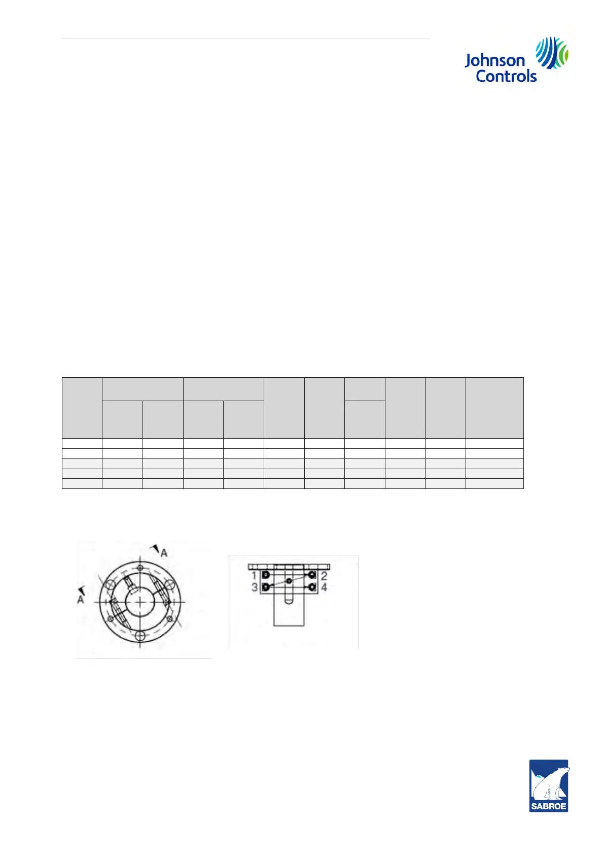
Fig. 84: Clamp hub design
Tighten the clamp screws in three stages. With each stage, follow the tightening sequence pat-
tern shown in section A-A in Fig. 84.
1. Hand tighten with an Allen wrench.
2. Tighten to half the clamp screw tightening torque value shown in Table 46 (according to
the coupling size).
3. Tighten to the full clamp screw tightening torque value shown in Table 46 according to
the coupling size. Continually repeat the tightening sequence of section A-A until all
 Loading...