INTEGRA/-S/-G/-GS User Manual WEB GUI
SAF Tehnika JSC
same (e.g. 40MHz) for both links. All other parameters can differ but keep in mind
that in the 2+0 configuration frequencies must differ, but in the 1+1 configuration
frequencies must be the same;
4. Both links should be polarized according to ACCP (Adjacent Channel Co-Polarized)
or ACAP (Adjacent Channel Alternate-Polarized) principles. CCDP (Co-Channel
Dual-Polarization) operation of both on the same frequency channel and opposite
polarizations is not allowed. In the case of ACCP a guard band equal to ¼ BW
should be introduced (e.g. 20MHz in the case of 80MHz channels).
5. Configure different IP addresses for all 4 Integra/Integra-S/Integra-G/Integra-GS
FODUs.
6. The remote IP address for all units must be entered manually. To do that, remove
the selection in the “Auto” checkbox and afterward enter the appropriate remote IP
address in the menu ”IP configuration” (please refer to Chapter System →
Configuration → IP configuration).
On both sides “Master” and “Slave” managements must be interconnected via an
external switch or directly on LAN1 or LAN3 ports (in addition to LAN2
interconnection) for aggregation/protection to work. This connection is used to
interchange 2+0/1+1 aggregation/protection statuses for proper operation.
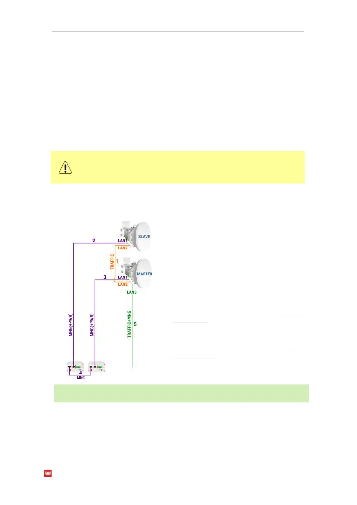
Interconnection schemes
There are 4 possible interconnection schemes:
1. Mandatory fiber optic cable between LAN2
(optical) ports on both units.
2. Electrical Ethernet cable (1000Base-T) between
PoE injector’s (#1) DATA+PWR port and LAN1
(electrical) port of the Slave FODU. Both data and
power are carried, therefore the total length of
cables #2, #3, and #4 combined should not
exceed 100m.
3. Electrical Ethernet cable (1000Base-T) between
PoE injector’s (#2) DATA+PWR port and LAN1
(electrical) port of Master FODU. Both data and
power are carried, therefore the total length of
cables #2, #3, and #4 combined should not
exceed 100m.
4. Electrical Ethernet cable (1000Base-T) between
PoE injectors’ (#1 and #2) DATA ports. Provides
management access to Slave FODU. The total
length of cables #2, #3, and #4 combined should
not exceed 100m.
5. Fiber optic cable between LAN3 (optical) port of
the Master or Slave FODU and CPE for both traffic
and management traffic.
Advantages: 1) external switch not required; 2) length of optical cable for traffic/management up to
10km.
 Loading...