Safco Products Company, New Hope, MN 55428
3957-37EN: 2 of 4; Rev. 2; 02/06
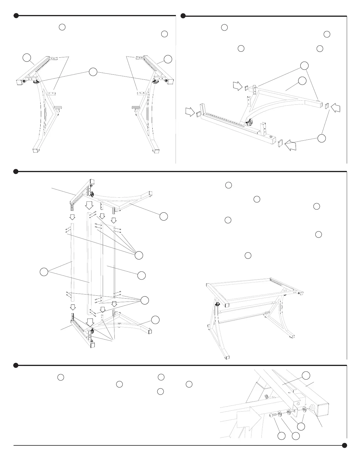
1
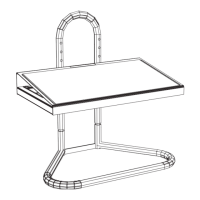
2
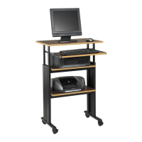
3
Locate the A Left Frame Assembly (the short chan-
nels will be on the right side of the frame), and the B
Right Frame Assembly (the short channels will be on
the left side of the frame).
ATTENTION!
Do NOT
unscrew the
ADJUSTMENT
KNOBS
until the final
instruction.
A
B
N
SHORT CHANNELS
Place the A Left Frame Assembly on a protected
surface with the short channels upward. Insert the
H Tube Plugs if they are not already installed on the
tube ends. Insert the O Levelers. Repeat with the B
Right Frame Assembly.
A
H
Insert the D Horizontal Tubes onto each of the short
channels along the upper end of the Left Frame As-
sembly. Attach using two J Long Pan Head Machine
Screws for each tube. Insert one end of the C Back
Panel onto the two lower short channels and attach
using four J Long Pan Head Machine Screws.
With the help of an assistant, carefully lift the B Right
Frame Assembly up and insert the short channels into
the open ends of the tube and back panel. Loosely
fasten using eight J Long Pan Head Machine Screws.
Carefully turn the assembled base upright.
A
C
B
D
J
J
SHORT
CHANNELS
UPPER
END
OF LEFT
FRAME
ASSEMBLY
UPPER
END
OF RIGHT
FRAME
ASSEMBLY
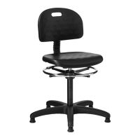
4
Place one L Nylon Spacer on the pin. Insert the G Support
Channel onto the pin. Place one L Nylon Spacer and one M
Washer on the pin and fasten securely using one R Short Pan
Head Machine Screw. Repeat for the other support channel
and frame.
M
L
R
FRAME
G
HINGE
PIN
Do Not
Overtighten.
O