Safco Products Company, New Hope, MN 55428
3957-37EN: 3 of 4; Rev. 2; 02/06
5
6
7
8
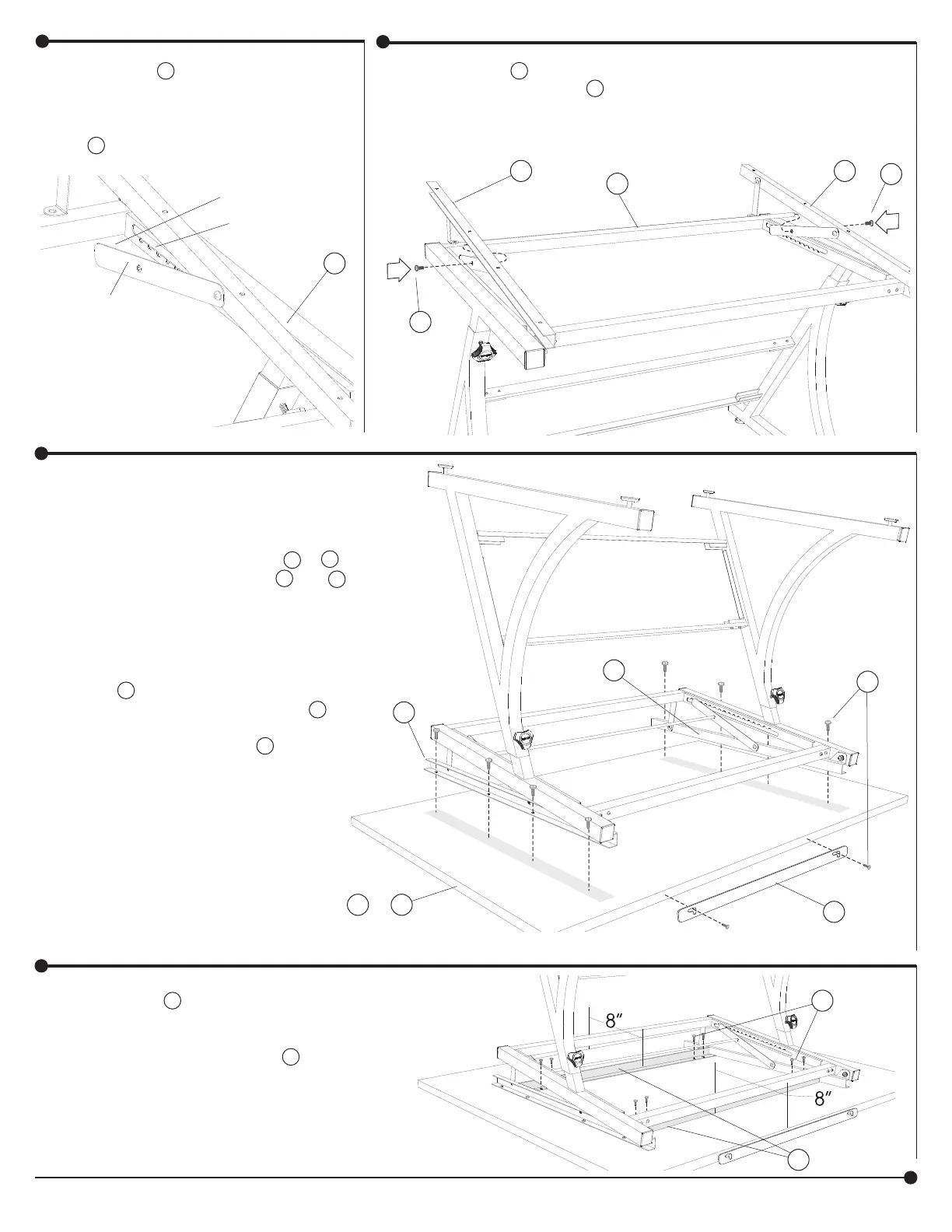
NOTCHED
CHANNEL
CHANNEL
PIN
CHANNEL
ARM
G
Raise the G Right Support Chan-
nel and insert the channel pin into
the notched channel in the frame.
Repeat this procedure for the
F Left Support Channel.
Attach the E Lift Bar to each channel arm through the coun-
tersunk holes using one I Large Flat Head Machine Screw at
each end.
E
F
I
I
G
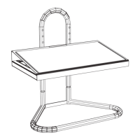
Prepare the Drawing Board.
Carefully open the Drawing Board
carton. Keep the Drawing Board in the
carton. Two people are required to lift
the assembled base onto the S or T
Drawing Board. Position the F and G
support channel assemblies located
on the base onto the drawing board.
Carefully center the frame from side-
to-side and front-to-back. Fasten the
support channels to the drawing board
using K Pan Head Hi-Grip Screws
through each channel. Attach the Q
Pencil Bar to the front edge of the
drawing board using two K Pan Head
Hi-Grip Screws.
NOTE: if it is too difficult to get
the screws into the board, position
the base and use a hammer and nail
to carefully tap starter holes using the
channel holes as a guide. Then, finish
fastening the screws to the board.
T
S or
K
G
F
Q
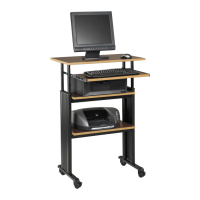
Position the P Support Bars in between the left
and right support channels. The Support Bars must
be placed at least 8" in from the long edges. Attach
to the Drawing Board using four K Pan Head Hi-
Grip Screws for each Support Bar.
When the frame is securely fastened to the
Drawing Board, turn the entire assembly upright.
P
K