Do you have a question about the Safeline EVAC and is the answer not in the manual?
Details power, inputs, outputs, size, weight, and IP code for the main unit.
Specifies power, inputs, outputs, and IP code for floor and car stations.
Lists power, inputs, relay outputs, and PSU for the LMS unit.
Covers the maximum cable length for the bus cable.
Emphasizes professional installation, intended use, modifications, and general safety standards.
Manufacturer's liability limitations regarding accidents, misuse, incorrect installation, and unauthorized changes.
Information on downloading the declaration of conformity from the website.
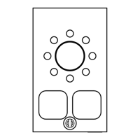
Provides detailed mounting dimensions for Entrance station, LMS Unit, Floor station, and Car station.
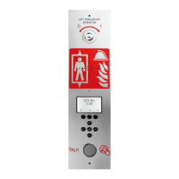
Describes the components of the Entrance Station: Switch, Speaker, Microphone, Display, Function keys, PTT.
Details the SD card slot and USB port for firmware updates.
Describes CAN termination, outputs, inputs, speaker, and RJ45 port.
Explains the function of CAN ERR and System LEDs.
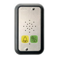
Details the components of the floor station: Speaker, Microphone, and Alarm button with LED.
Covers RJ45 port, CAN termination switch, and USB port for firmware updates.
Describes inputs, outputs, SD card, and bus address selectors.
Shows the location of the alarm button.
Details the speaker and microphone components of the car station.
Describes RJ45, CAN termination, USB, LEDs, SD card, and bus address selectors.
Lists and explains the 7-pin connector terminals for power, CAN bus, and audio.
Explains the RJ45 connector for floor or car stations.
Explains the LMS unit's role in sending messages and powering the EVAC system.
Defines the entrance station as the master unit controlling the system.
Details LED indicators, RS232, USB, CAN LEDs, termination switches, communication connectors, and PSU.
Explains the function of inputs and relay output changeover contacts.
Instructions on how to cut and prepare the connection cable with RJ45 plugs.
Describes the heartbeat message for unit identification and system status monitoring.
Explains how to assign unique addresses to units like car and floor stations.
Details the TERM switch settings for LMS, car, and floor stations on CAN buses.
Steps to enter the setup menu via key sequence and PIN.
Instructions for adjusting speaker volumes for Entrance, Car, and Floor stations.
Guide to setting display labels for nodes in EVAC/connect mode.
How to select and configure relay functions for the LMS unit.
Procedure to exit the setup menu and save changes.
Illustrates connections for power, CAN, inputs, and relay outputs on the LMS board.
Shows wiring for up to 2 car units and CAN 1 connection to floor stations.
Describes how to enter SETUP and CONNECT menus using key sequences and PIN.
How to change the default language from English to German.
Outlines methods for connecting to units in STANDBY and EVAC modes, and communication priority.
Describes how alarms are displayed and how to connect to them in the EVAC menu.
Explains how to connect to the car station in EVAC mode and floor stations with registered alarms.
Details parameter setup in the entrance station's SETUP menu and saving changes.
Describes the default idle state, allowing access to setup and connect menus.
Explains using the system for evacuation, triggering calls from floor stations.
Details the FIRE mode for intercom communication, often linked to fire fighter keys.
Explains the need for unique CAN-bus node IDs and addressing for floor stations.
Details STANDBY, EVAC, and FIRE modes for floor stations.
Defines the entrance station as the central control unit for the EVAC system.
Explains STANDBY, EVAC, and FIRE modes as they apply to the entrance station.
Covers max nodes, Fire Mode setup, Admin/User PINs, and Broadcast sound files.
Details test sound, date, time, and self-test configuration.
Explains reading config from SD, factory reset, and language selection.
Covers backlight, volume, input functions (PTT, FIRE, EVAC), and output functions (PTT_ACK, FIRE, EVAC).
Information on viewing hardware and software versions.
Details volume, mic level, input functions (Off, Alarm button), and output functions (Off, Alarm button ACK).
Settings for node state (active/inactive), labels, inputs, and outputs.
Adjusting speaker volume and configuring sound file playback modes.
Selecting nodes to indicate and viewing hardware/software versions.
Reading the log file and current errors from the system.
Settings for activating LMS triggers, sending test messages, and relay functions.
Information on hardware/software versions and LMS codes for triggers.
Explains the role of the SD card for logs and sound files on entrance and floor stations.
How floor stations can play sound files manually or automatically via triggers.
Describes the format of log entries: ENTRY, TIME, CODE, DATA.
Lists hex codes for various system events and errors.
Explains the 'i' symbol for errors and how to view the error list.
Lists common error codes and their meanings, with examples.
Lists product details, EC directives, and applied standards for conformity.
Contains signature and details of the Technical Manager.
| Brand | Safeline |
|---|---|
| Model | EVAC |
| Category | Intercom System |
| Language | English |