SAILFISH 245 DC |
40
3
A
B1–B2
1
2
1
2
3 4 5 6 7
Dometic MasterFlush
6
4 Components
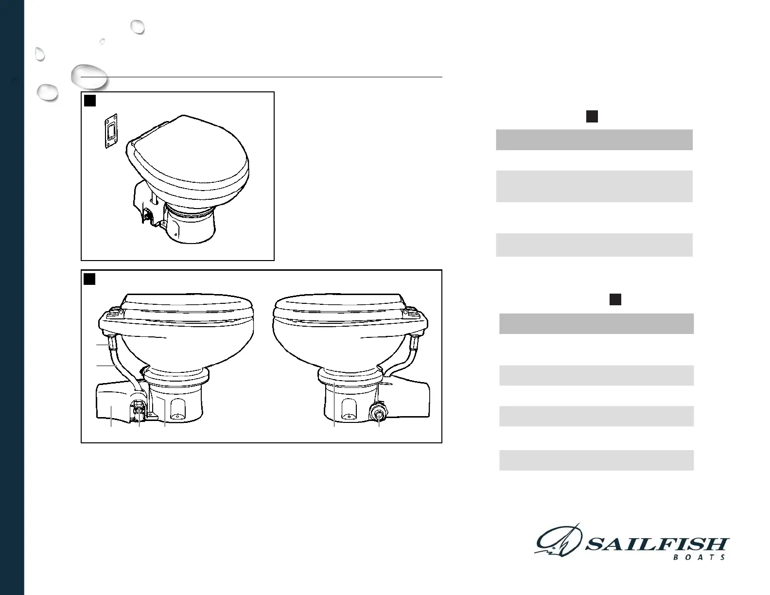
Installed toilet (g.
1
)
Toilet components (g.
2
)
5.2 Minimum System Requirements
5 Specifications
5.1 Materials
Toilet: vitreous ceramic
Toilet base: polypropylene
Dometic flush switch panel: polystyrene (DFS-1F or DFS-2F); or powder-coated aluminum
(DFST)
Electrical
Power draw 20 amps/12 V DC; 10 amps/24 V DC
Circuit breaker 25 amps/12 V DC; 15 amps/24 V DC
Wiring
12 ga. (up to 25 ft./7.6 m total circuit)
Consult ABYC guidelines for additional information.
Water
Supply
Fitting size
Supply hose ID
0.5 in. NPT – fresh water ush toilet
0.75 in. ID – sea water ush toilet
Flow rate 2.0 gpm/7.6 lpm minimum – fresh water ush
Discharge
Inside diameter 1.5 in./38 mm or 1 in./25 mm
Horizontal run* 40 ft./12.2 m maximum
Vertical run* 4 ft./1.2 m maximum
* Horizontal and vertical run distances are not cumulative. Check for adequate discharge ow
if installation nears one of these limits.
Specications are subject to change without notice.
Ref. Description
A Macerator toilet
B1 DFS-2F ush switch (standard -
freshwater ush toilet)
B2 DFS-1F ush switch (standard -
sea water ush toilet)
NS DFST ush switch (optional)
NOT SHOWN
Ref. Description
1 Rim ush check valve (freshwater
toilet) or adapter (sea water model)
2 Water supply hose
3 Macerator pump
(under plastic cover)
4 Electric water valve
5 Product ID label location
6 Stainless steel compression band
7 Discharge tting
Refer to complete parts list (packed separately)
for additional information.
Dometic MasterFlush
4 Components
Installed toilet (g.
1
)
Toilet components (g.
2
)
5.2 Minimum System Requirements
5 Specifications
5.1 Materials
Toilet: vitreous ceramic
Toilet base: polypropylene
Dometic flush switch panel: polystyrene (DFS-1F or DFS-2F); or powder-coated aluminum
(DFST)
Electrical
Power draw 20 amps/12 V DC; 10 amps/24 V DC
Circuit breaker 25 amps/12 V DC; 15 amps/24 V DC
Wiring
12 ga. (up to 25 ft./7.6 m total circuit)
Consult ABYC guidelines for additional information.
Water
Supply
Fitting size
Supply hose ID
0.5 in. NPT – fresh water ush toilet
0.75 in. ID – sea water ush toilet
Flow rate 2.0 gpm/7.6 lpm minimum – fresh water ush
Discharge
Inside diameter 1.5 in./38 mm or 1 in./25 mm
Horizontal run* 40 ft./12.2 m maximum
Vertical run* 4 ft./1.2 m maximum
* Horizontal and vertical run distances are not cumulative. Check for adequate discharge ow
if installation nears one of these limits.
Specications are subject to change without notice.
Ref. Description
A Macerator toilet
B1 DFS-2F ush switch (standard -
freshwater ush toilet)
B2 DFS-1F ush switch (standard -
sea water ush toilet)
NS DFST ush switch (optional)
NOT SHOWN
Ref. Description
1 Rim ush check valve (freshwater
toilet) or adapter (sea water model)
2 Water supply hose
3 Macerator pump
(under plastic cover)
4 Electric water valve
5 Product ID label location
6 Stainless steel compression band
7 Discharge tting
Refer to complete parts list (packed separately)
for additional information.
Dometic MasterFlush
OWNER'S MANUAL - OPTIONAL TYPE III MSD WASTE
MANAGEMENT SYSTEM