What’s in the box?
What do I need to fi t it?
How to install the VHF on desktop and overhead
How to install the VHF fl ush mount
INSTALLATION GUIDE
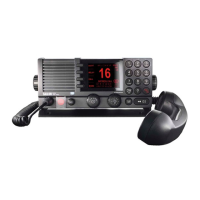
SAILOR 6248 VHF
Thrane & Thrane A/S
•
info@thrane.com • thrane.com
98-132282-A
How to install the handset
Power Drill Jigsaw Screwdriver
TORX 20
Drill for M4 or
Ø3.9 self-tapping
U-Mounting
Bracket
Gasket
Flush Mount
Bracket (2 pcs.)
Fuse
6.3x3.2mm
(10AT)
Cradle
Wheel Knob
(2 pcs.)
Screw M4x45
TORX 20
(5 pcs.)
Square Nut
M4x7x2.2
(5 pcs.)
Screw M4x12
TORX 20 (2 pcs.)
Screw ø3.9x19
TORX 20 (2 pcs.)
Screw M4x12
TORX 20
(5 pcs.)
Screw ø3.9x19
TORX 20
(5 pcs.)
Handset
Very important information!
Do not remove the membrane.
If you remove the membrane the
radio will not be waterproof.
This Handset has a hook-on/off function,
which is activated by a small magnet embedded
in the cradle.
The cradle must be installed as illustrated in
order to ensure the hook-on/off functionality
of the Handset.
75mm
62mm
226mm
* 120mm
min. 100mm
Space for handset access
Space for cable and handset cable
54mm
45mm
135mm
39655C