2 INSTALLATION
AT2112
2.3 AERIAL AND GROUND
AERIAL
Most important for good communication
is
the aerial. The best efficiency of the aerial will
be
with the
aerial coupler AT2112 mounted outdoors, close to the footpoint of the aerial and the aerial placed
as
high and free
as
possible. The aerial coupler AT2112 has to
be
grounded carefully.
AERIAL LENGTH
Max. length
16
meters, min. length 9 meters. The aerial length
is
measured from the insulator on
AT2112 to the top
of
the aerial.
lf the transmitter tias to work mainly on frequencies below
4 MHz a total aerial length of 15 meters
is recommended.
lf the transmitter has
to
work mainly on frequencies higher than 4 MHz
an
8.5 meters whip aerial is
recommended.
GROUND
The grounding points
on
AT2112 are the four mounting foots. lt
is
must important that these are
in
god contact with the ground,
eg.
the wheel house.
AT2112 has to
be
grounded at the footpoint of the aerial.
lf a metal wheel house, weid up a pillar for AT2112 and bolt it
to
the pillar. This way you get the best
ground for your antenna system.
lf a wooden or fibre glass boat, connect
all
accessible metal parts together and connect them to the
aerial coupler with a copper strip
(100 x 0.5 mm), making the copper strip as short
as
possible. You
can also make
an
artificial ground under the aerial coupler
as
shown in example
5.
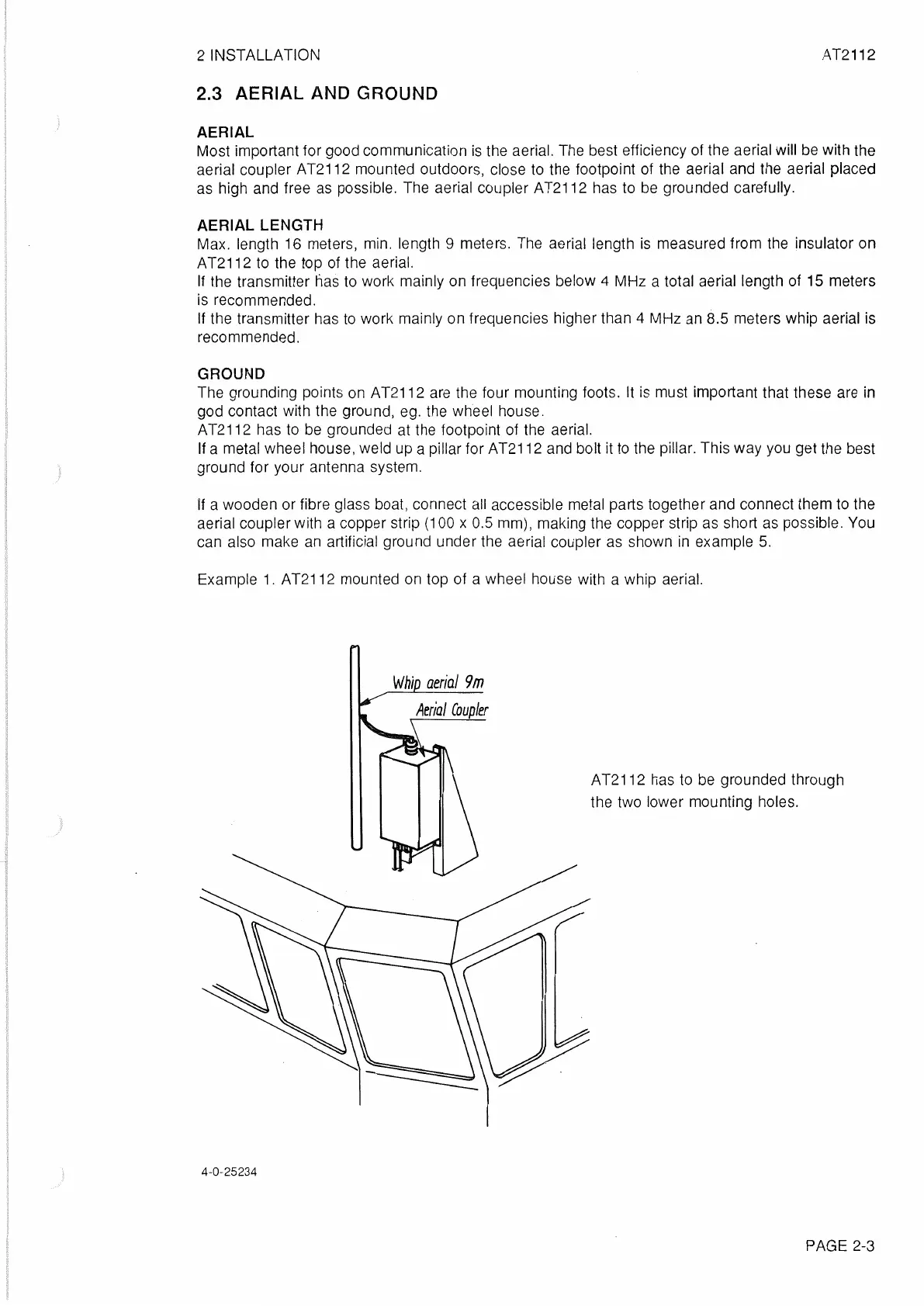
Example
1.
AT2112 mounted
on
top of a wheel house with a whip aerial.
Whip
aerial
9m
4-0-25234
AT2112 has to
be
grounded through
the two lower mounting holes.
PAGE 2-3
 Loading...