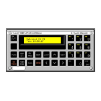
4 MECHANICAL DESCRIPTION
4.1 MECHANICAL DISASSEMBLING AND UNITS LOCATION
Screw for front plate
Screw for cover
Top view
Screw for Display section
Front view without frontplate
Buttom view
Balanced AF-output
level adjustment
Unbalanced AF-output
level adjustment
Key information switch
DSC AF-output
selection switch
Screw for Microprocessor module
Cable for Display module
Remove indicated cable and screws for removal of Micro-
processor module, and draw the module gently toward the
front
Clock backup battery
Switch for mode select
727499 727498
501225 501226 501227
501229 501232 501236
RM2042
PAGE 4-1