5 CIRCUIT DESCRIPTION AND SCHEMATIC DIAGRAMS RM2042
PAGE 5-18
9341
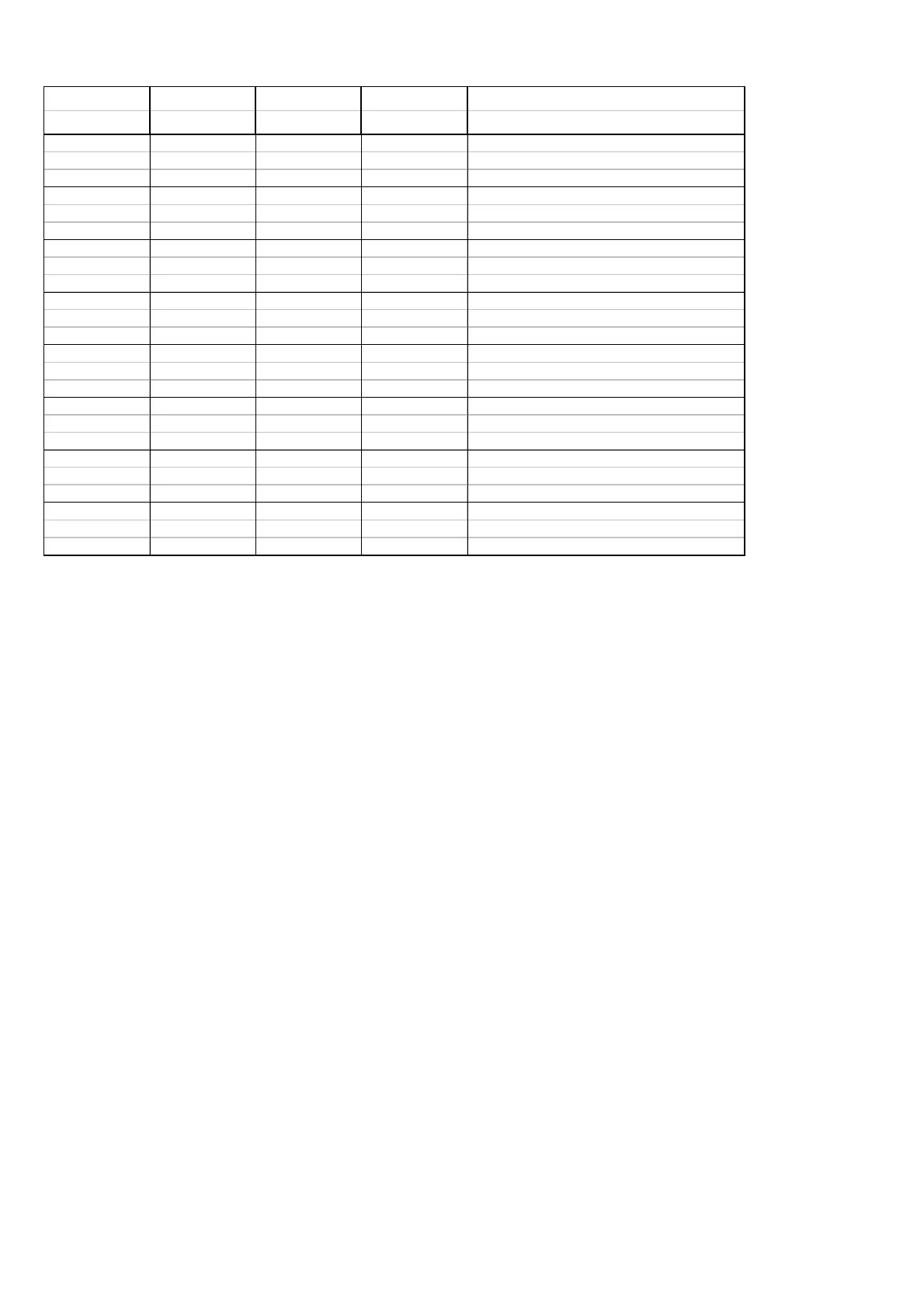
CH70 CARRIER VHF CARRIER AF SIGNAL MODULATION REMARKS
DETECT DETECT DETECT DETECT
No carrier detected at CH70 receiver,
0000and no carrier detected at ext. VHF.
Af signal detected because of noise.
0010 Non existing combination.
No carrier detected at CH70 receiver,
0101byt carrier detected at ext. VHF.
AF signal detected from ext. VHF.
No carrier detected at CH70 receiver,
0110but carrier detected at ext. VHF.
No AF signal detected from ext. VHF.
Carrier detected at CH70 receiver,
1001and no carrier detected at ext. VHF.
AF signal detected from CH70 receiver.
Carrier detected at CH70 receiver,
1010and no carrier detected at ext. VHF.
No AF signal detected from CH70 receiver.
Carrier detected at CH70 receiver,
1101and carrier detected at ext. VHF.
AF signal detected from CH70 receiver.
Carrier detected at CH70 receiver,
1110and no carrier detected at ext. VHF.
No AF signal detected from CH70 receiver.
5V SUPPLY
The 5V supply is generated from the battery voltage by the series voltage regulator U11.
This regulator is of the type 78L05AC, which is able to deliver a current of about 50mA without any heat
sink.
10V SUPPLY
The 10V supply is generated from the battery voltage by the series voltage regulator U10, which is of the
type LP2951C. The output voltage is determined by four feed back resistors (R121 to R124) and is
adjustable by means of the trimming resistor R124.
The LP2951C has a build-in facillity for generating an error signal, when the output voltage drops more
than 5% with respect to the programmed output voltage. This error signal is watch every one milli second
by the microprocessor to ensure a controlled power down sequence.