16 | EN SMARTY v2023.2
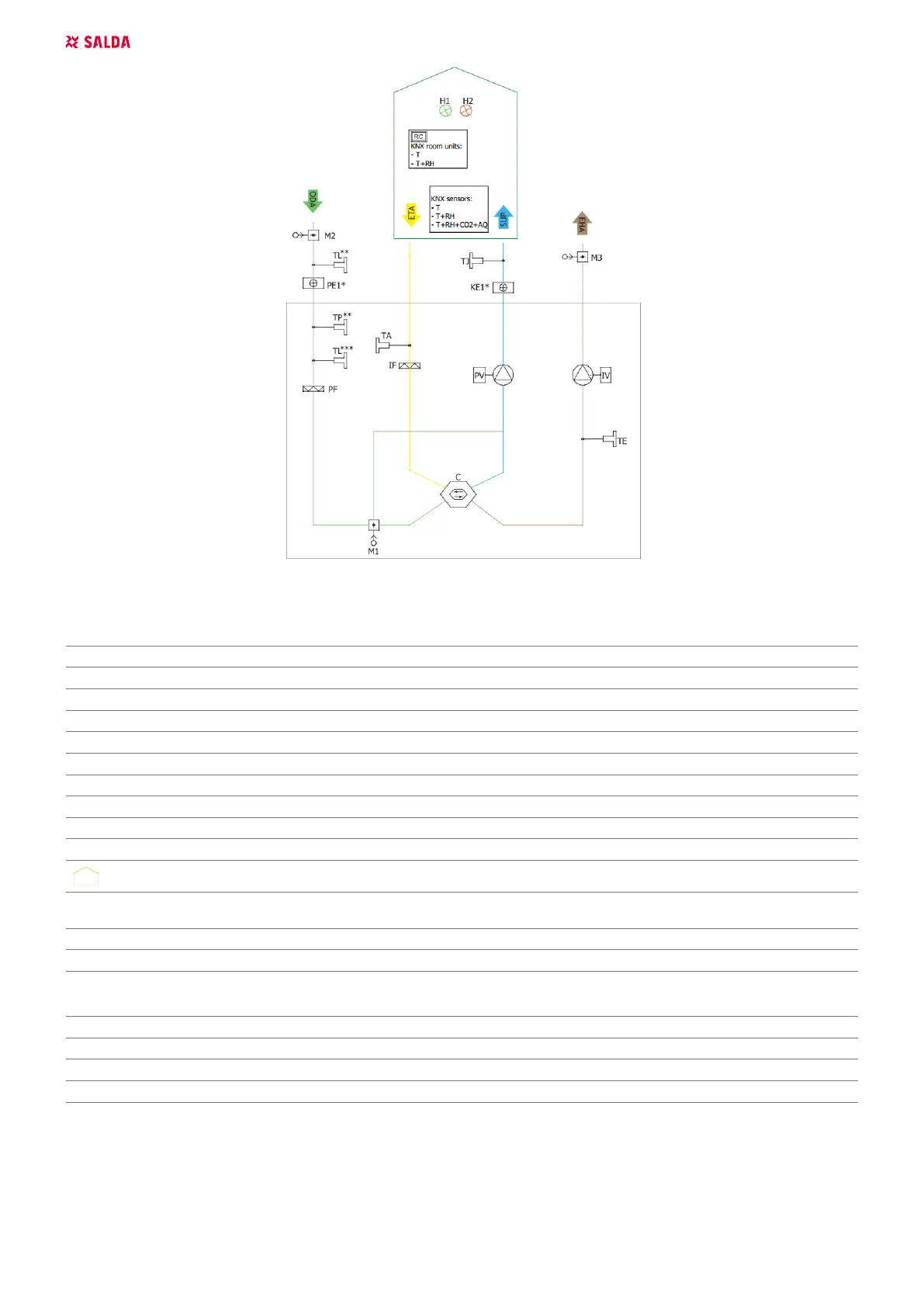
Figure 5.4.6. SMARTY XV S300 (* Only heater or preheater can be connected at a time; ** Components connection only with PE1;
*** Components connection only without PE1)
THE LIST OF COMPONENTS
C Plate heat exchanger PV Supply air fan
IF Extract air lter PF Supply air lter
IV Exhaust fan TA Extract air temperature sensor
TE Exhaust air temperature sensor TJ Supply air temperature sensor
DTJ Extract air temperature and humidity sensor* CO
2
CO
2
sensor*
RH Air humidity sensor* PC Computer*
KE1 Electric heater PE1 Electric pre-heater
M1 By-pass damper M2 Outdoor air damper actuator
M3 Exhaust air damper actuator SK1 Supply air pressure sensor*
SK2 Exhaust air pressure sensor* TL Outdoor air temperature sensor
Ventilated premises MB-Gateway Network module*
NET Network* RC
Stouch, ST-SA-Control, POS8.4420 or POS8.4440
remote control panel*
TP Air temperature after preheating coil sensor* AQ Air quality sensor*
T Temperature sensor*
* Component/possibility to connect it depends on model.
POSSIBLE PCB INPUTS/OUTPUTS
FA Fire alarm FPP Fireplace protection
H1 Operation/Working indication output H2 Alarm indication output
System mode switch Fans speed switch
5.5. MOUNTING
• Installation works should be carried out by qualied and trained sta only.
• When connecting air ducts, consider the labels on the casing of the unit.
• Before connecting to the air duct system, the connection openings of the ventilation unit should be closed.
• When connecting the ducts, the air-ow direction indicated on the device housing should be observed.
 Loading...