Do you have a question about the Sam4s SPS-500 Series and is the answer not in the manual?
General safety guidelines to prevent damage and hazards during servicing.
Precautions to follow during servicing to avoid damage and ensure safety.
Guidelines for handling ESD sensitive components to prevent damage.
Detailed general specifications for the SAM4S SPS-500 Series POS system.
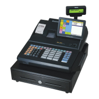
Information on the physical appearance and dimensions of the POS system.
Physical dimensions of the POS system with different drawer options.
Identifies the location of various components and ports on the POS system.
General specifications for the SAM4S SPS-530 POS system.
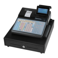
Physical appearance and dimensions for the SPS-530 POS system.
Physical dimensions of the SPS-530 POS system with different drawer options.
Identifies components on the SPS-530 POS system.
Technical specifications for the thermal printer models.
Technical specifications for the 2-inch thermal printer model.
Details about the paper type and size compatible with the printer.
Information on the usable printing area on the paper.
Specifications for character printing, including size and layout.
Technical specifications for the 3-inch thermal printer model.
Paper specifications for the 3-inch thermal printer.
Printable area details for the 3-inch printer.
Character specifications for the 3-inch printer.
Details on power input voltage, current, and consumption.
Power input voltage, current, and consumption details.
Technical details for various interface ports.
Technical details of the RS-232C serial interface, including baud rates and flow control.
Detailed pinout and signal descriptions for RS-232C connectors.
Wiring diagrams for RS-232C interface cables connecting the POS to user devices.
Details of the USB interface, including transfer type, data format, and speed.
Pinout and signal descriptions for USB connectors.
Signal descriptions for LAN connections, including transmit and receive lines.
Wiring diagrams for LAN interface cables used for communication.
Signal descriptions for the cash drawer interface.
Wiring diagram for the cash drawer interface cable.
Steps to set up TFTP32 for OS and application updates from a PC.
Configuration steps for the TFTP32 software, including settings and base directory.
Preparation steps for program updates, including PC connection and network settings.
Procedure for updating the OS and application, involving DIP switch verification and key presses.
Steps for formatting the SD card with FAT-32 file system for updates.
Procedure to format an SD card using the FAT-32 file system.
Preparation steps for SD card updates, including directory creation and file copying.
Procedure for OS and application updates using an SD card, involving DIP switches and key presses.
Steps for updating the boot area from a PC.
Steps for updating the boot area from an SD card.
Procedure to update the CPU on the IO board from a PC.
Procedure to update the IO board CPU from an SD card.
Steps to update the LCD board CPU from a PC.
Procedure to update the LCD board CPU from an SD card.
Procedure for updating the boot area when it is corrupted.
Guide to performing hardware self-tests on the POS system.
Instructions for testing the display and touch screen functionalities.
Procedure for testing the SRAM memory, noting that it clears all memory.
Instructions for performing loop-back tests on communication interfaces.
Instructions for testing flash memory, SD card, Dallas key, MSR, and Printer.
Procedure for testing the Real-Time Clock (RTC) functionality.
Guide for testing the keyboard and mode keys.
Instructions for testing the printer, including print and cutter functions.
Steps for testing the SD card functionality.
Procedure to check for bad blocks in the NAND flash memory.
Steps for system setup, starting with DIP switch verification.
Instructions for writing the MAC address through the setup menu.
Steps to access MCR track information.
Instructions for adjusting printer density settings.
Procedure to select the keyboard type.
Configuration for serial port power output.
Instructions for adjusting the LCD backlight.
Overview of system configuration options and network setup.
Diagram illustrating system configuration with multiple POS units.
Information on optional features and supplies for the POS system.
List of optional features available for the POS system.
List of supplied items, such as paper rolls and user manuals.
Step-by-step instructions for installing paper rolls in the SPS-520 printer.
Step-by-step instructions for installing paper rolls in the SPS-530 printer.
Instructions for installing the take-up spool for the printer.
Procedure for installing the Magnetic Stripe Reader (MSR) assembly.
Further steps for connecting and securing the MSR assembly.
Shows the MSR assembly in its final installed position.
Cautionary notes and steps for installing a memory card.
Cautionary notes and steps for uninstalling a memory card.
Initial setup note and explanation of mode switch positions and functions.
Explanation of how the mode switch position affects POS actions and lists modes/keys.
Procedure to clear all totals and programming data, returning the register to default.
Steps for disassembling the upper casing of the POS system.
Steps to open and lift the ASS'Y COVER PRINTER and remove screws.
Steps to separate the LCD display assembly from the upper case.
Procedure to separate the turret assembly and rear display.
Steps to separate the mode switch cover and its components.
Steps for disassembling the lower casing of the POS system.
Steps to disassemble the auto cutter assembly for SPS-520.
Steps to disassemble the printer assembly for SPS-520.
Steps to disassemble the printer assembly for SPS-530.
Procedure to disassemble the spool motor assembly for SPS-520.
Steps to disconnect FPC cables and lift the keyboard assembly.
Procedure to disconnect the harness and lift the Dallas Key assembly.
Steps to separate harnesses and screws for I/O and Main PBA.
Procedure to separate harnesses and lift the USB PBA.
Cautions and steps for disassembling the auto cutter block.
Detailed steps for disassembling the cutter assembly, including removing screws and parts.
General maintenance procedures for the POS system.
Instructions for cleaning the printer head to maintain print quality.
Steps to clear paper jams from the SPS-520 printer.
Steps to clear paper jams from the SPS-530 printer.
Lists the sequence of events during POS system power-up for diagnostics.
Describes the power-up sequence for the Main Board.
Describes the power-up sequence for the IO Board.
Describes the power-up sequence for the LCD Board.
Troubleshooting steps for power-related issues on the POS system.
Checks to perform on the power supply and AC cord.
Troubleshooting steps for power lines on the IO Board.
Troubleshooting steps for power lines on the Main Board.
Troubleshooting steps for power lines on the LCD Board.
Troubleshooting for Main Board issues related to system boot and programs.
Identifies issues with the boot flash ROM on the Main Board.
Troubleshooting for Main Board problems with application programs.
Troubleshooting for Main Board issues related to backlight, LCD, memory, RTC, and battery.
Diagnosing issues with the TFT-LCD backlight.
Troubleshooting steps for TFT-LCD panel display problems.
Diagnosing data memory backup failures when power is off.
Troubleshooting for Real-Time Clock (RTC) issues.
Information and troubleshooting related to the system battery.
Troubleshooting for Main Board issues related to LAN, USB, and Serial communication.
Troubleshooting LAN connectivity and communication failures.
Troubleshooting USB device attachment and communication failures.
Diagnosing communication failures and voltage issues for serial ports.
Troubleshooting SD card operation failures.
Troubleshooting for LCD Board issues including boot, panel, touch, rear LCD, and LED.
Diagnosing boot problems on the LCD Board.
Troubleshooting steps for LCD panel issues like no display.
Diagnosing problems with the touch panel functionality.
Troubleshooting for issues with the rear LCD display.
Diagnosing problems with the LED Board.
Troubleshooting for IO Board issues related to boot, printer, feed motor, and auto-cutter.
Diagnosing boot flash ROM problems on the IO Board.
Troubleshooting steps for the thermal printer.
Diagnosing issues with the auto-cutter function.
Provides an overview and exploded view of the main POS set.
Visual representation of the total disassembly of the SPS-520/SPS-530 main set.
Exploded view and parts list for the LCD assembly.
Exploded view and parts list for the printer cover assembly (SPS-520).
Exploded view and parts list for the printer cover assembly (SPS-530).
Exploded view of the upper case assembly.
Exploded view of the printer assembly for SPS-520.
Exploded view of the printer assembly for SPS-530.
Exploded view of the auto cutter assembly (SAC-70).
Exploded view of the 90-key keyboard assembly.
Exploded view of the 160-key keyboard assembly.
Exploded view of the lower case assembly.
Exploded view of the MSR assembly.
Exploded views of the different drawer assemblies.
Exploded view of the Aplus Drawer assembly.
Exploded view of the G-Drawer (4B8C, 5B6C) assembly.
Exploded view of the G-Drawer (5B8C) assembly.
Layout and parts list for the Main PCB.
Layout and parts list for the I/O PCB.
PCB layout and parts list for the CF card.
PCB layout and parts list for the LCD.
PCB layout and parts list for SD, Converge, LED, and USB boards.
PCB layout and parts list for the SPS-520 2-inch joint board.
PCB layout and parts list for the SPS-530 3-inch joint board.
Block diagram showing the connections on the Main PBA.
Detailed wiring connections for the Main PBA with various connectors.
Block diagram illustrating the connections on the IO PBA.
Detailed wiring connections for the IO PBA, covering various connectors.
Block diagram showing connections on the LCD PBA.
Detailed wiring connections for the LCD PBA.
Block diagrams for SD, LED, Converge, and USB PBAs.
Block diagram for the 3-inch PRT joint PBA.
Block diagram for the SRAM (CF TYPE) PBA.
Block diagram for the 2-inch PRT joint PBA.
Schematics for the Main PCB, including CPU, memory, LAN, and power.
Schematics for the I/O PCB, covering CPU, memory, KBD, and various interfaces.
Schematics for the LCD PCB, including main interface and MICOM.
Schematics for SD, USB, LED, and Convert PCBs.
Schematic for the SRAM Memory PCB.
Schematic for the 2-inch Printer Joint PCB.
Schematic for the 3-inch Printer Joint PCB.
| Brand | Sam4s |
|---|---|
| Model | SPS-500 Series |
| Category | Cash Register |
| Language | English |