SAMLEX AMERICA INC. | 73
SECTION 4 | Parameter Setup
i. First, the frequency of the Inverter Section is tracked in steps of 0.1Hz per cycle and made
equal to the frequency of the Grid / Inverter Generator input.
ii. Then, the phase of the Inverter voltage relative to the Grid voltage is tracked by 1º per cycle.
When the phase of the Inverter voltage is within ± 3.5º of the input voltage waveform, the
Transfer Relay is activated to transfer the AC load from the Grid / Inverter Generator to the
Inverter Section at zero crossing of the voltage waveform.
b) Parameter SYNC GRID set at Option 1= Coarse
This setting is selected if a Generator is connected to AC Input Terminals marked “GRID” (4,5,6 in
Fig 2.3 in Owner’s Manual for EVO-2212/3012/2224/4024). As compared to very stable frequency
of Grid / Inverter Generator, the frequency of a Generator may vary considerably depending upon
the performance of its Speed Governor that compensates for the drop in RPM / frequency when
electrical load is switched on / increased or, rise in RPM / frequency when electrical load is decreased
/switched off. Hence, if synchronization sensitivity set is at “0= Fine” as in Section 4.5.2.9 (a)
above, it may take very long for the Inverter Section to synchronize with the Generator or, may
not synchronize at all. Under this option, the frequency and phase of the Inverter Section are
synchronized with the Generator differently as follows:
i. First, the frequency of the Inverter Section is NOT tracked at 0.1Hz per cycle as in Option “0=
Fine” [See Section 4.5.2.9(a) above] but is made equal to the Generator frequency at zero
crossing of the Inverter voltage.
ii. Then, the phase of the Inverter voltage relative to the phase of the Generator / Inverter
Generator voltage is tracked by 1º per cycle. When the phase of the Inverter Section is within
± 10.5º of the Generator input voltage waveform, the Transfer Relay is activated to transfer
the AC load from the Generator to the Inverter Section at zero crossing of the voltage
waveform.
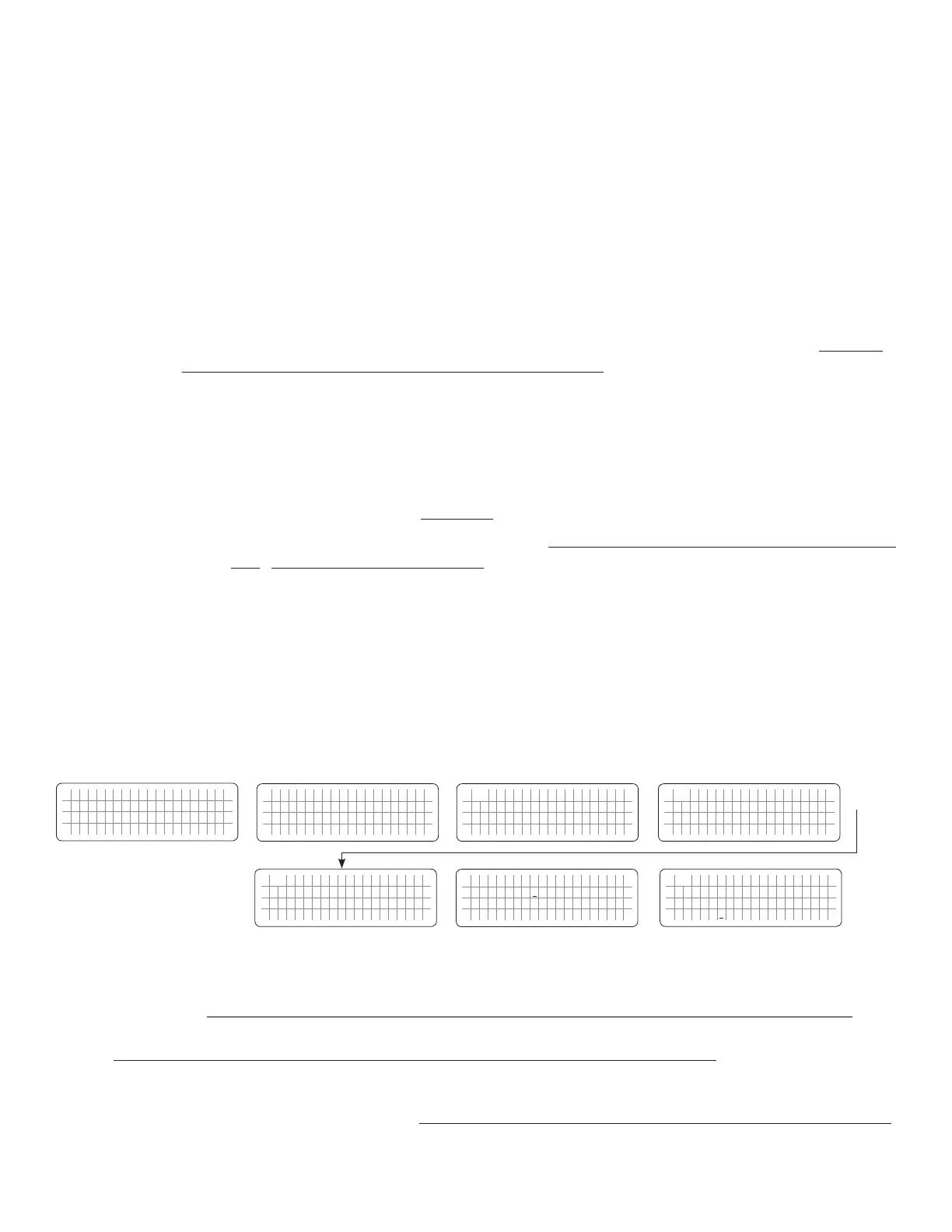
4.5.2.9.1 Programming Steps for Parameter “SYNC GRID”
ð ð
E V O - 1 2 1 2 F I n v e r t i n g
A C o u t p u t : 1 2 0 . 0 V
< 0 . 1 0 A
6 0 . 0 0 H z
Enter Key
Down Key x 7 times for
EVO-2212/3012/2224/4024
Any Operating Mode Screen from
Fig 3.1 to 3.5
[Above screen is Screen 1 of Fig 3.2(a)]
Password 8052
See Section 4.3.1
For programmable options, see Table 4.6,
Parameter Setup Screen No. 8 under
Column 2 for EVO-2212/3012/2224/4024
S e l e c t G r o u p
* C H A R G E C U R V E
ð
S e l e c t P a r a m e t e r
* I N P U T S E T T I N G
ð
S e l e c t P a r a m e t e r
I N P U T S E T T I N G
* D E F A U L T F R E Q
0 = 6 0 H z
S e l e c t P a r a m e t e r
I N P U T S E T T I N G
* S Y N C G R I D
0 = F i n e
Down Key x 1 time
Enter Key
P a s s w o r d k e y i n
0 0 0 0
ð
Enter Key
S e l e c t P a r a m e t e r
I N P U T S E T T I N G
* S Y N C G R I D
0 = F i n e
ð
Enter Key
4.5.2.10 SYNC GEN (Table 4.6, Parameter Setup Screen No. 9 under Column 2 for EVO-2212/3012/2224/4024)
NOTE: Parameter "SYNC GEN" is not available for EVO-1212F/1212F-HW/1224F/1224F-HW
In EVO-2212/3012/2224/4024, the frequency and phase of the Inverter Section are always kept synchronized with the AC
input source connected to terminals marked “GEN” (7,8,9 in Fig 2.3 in Owner’s Manual for EVO-2212/3012/2224/4024).
This facilitates faster and safer transfer of power between the Inverter Section and the AC input source.
 Loading...