SAMLEX AMERICA INC. | 75
SECTION 4 | Parameter Setup
ii. Then, the phase of the Inverter voltage relative to the phase of the Grid / Inverter Generator
voltage is tracked by 1º per cycle. When the phase of the Inverter voltage is within ± 3.5º of
the input voltage waveform, the Transfer Relay is activated to transfer the AC load from the
Grid / Inverter Generator to the Inverter Section at zero crossing of the voltage waveform.
4.5.2.10.1 Programming Steps for Parameter “SYNC GEN”
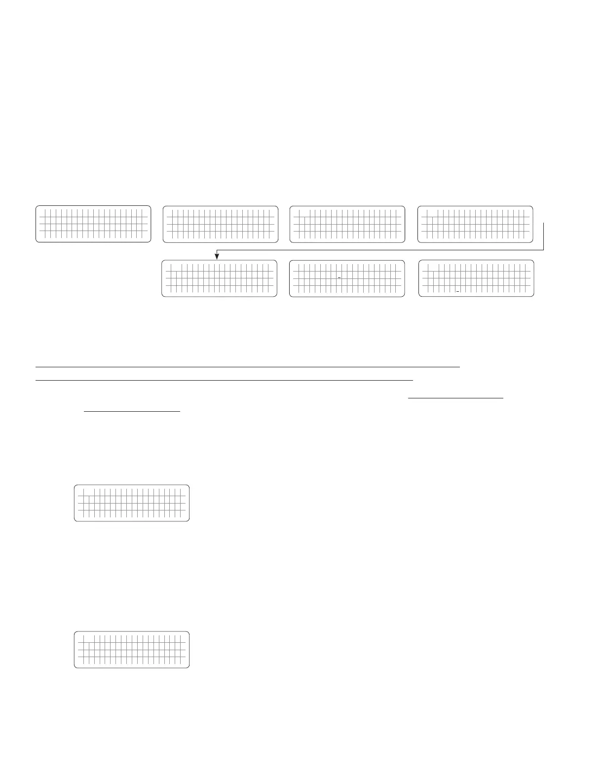
ð ð
E V O - 1 2 1 2 F I n v e r t i n g
A C o u t p u t : 1 2 0 . 0 V
< 0 . 1 0 A
6 0 . 0 0 H z
Enter Key
Down Key x 8 times for
EVO-2212/3012/2224/4024
Any Operating Mode Screen from
Fig 3.1 to 3.5
[Above screen is Screen 1 of Fig 3.2(a)]
Password 8052
See Section 4.3.1
For programmable options, see Table 4.6,
Parameter Setup Screen No. 9 under
Column 2 for EVO-2212/3012/2224/4024
S e l e c t G r o u p
* C H A R G E C U R V E
ð
S e l e c t P a r a m e t e r
* I N P U T S E T T I N G
ð
S e l e c t P a r a m e t e r
I N P U T S E T T I N G
* D E F A U L T F R E Q
0 = 6 0 H z
S e l e c t P a r a m e t e r
I N P U T S E T T I N G
* S Y N C G E N
0 = F i n e
Down Key x 1 time
Enter Key
P a s s w o r d k e y i n
0 0 0 0
ð
Enter Key
S e l e c t P a r a m e t e r
I N P U T S E T T I N G
* S Y N C G E N
0 = F i n e
ð
Enter Key
4.5.2.11 INPUT OC PROTECT
(Table 4.6: (i) Parameter Setup Screen No.8 under Column 1 for EVO-1212F/1212F-HW/1224F/1224F-HW
(ii) Parameter Setup Screen No.10 under Column 2 for EVO-2212/3012/2224/4024)
If the net AC input current is 1A more than the value of GRID MAX CURRENT (See Section 4.5.2.2) or GEN MAX
CURRENT (See Section 4.5.2.3) for 1 sec, the AC side charging current is clawed back to ensure that GRID MAX
CURRENT / GEN MAX CURRENT value is not exceeded. If the value of pass through load current increases to a value
of 1A more than the programmed value of GRID MAX CURRENT / GEN MAX CURRENT for 5 sec, input over current
protection will be activated based on the following 2 options provided through parameter INPUT OC PROTECT:
a) Option "0=INV mode" (Default Option). Set up screen is shown below:
S e l e c t P a r a m e t e r
I N P U T S E T T I N G
* I N P U T O C P R O T E C T
0 = I N V m o d e
o If the AC input current is 1A more than the programmed value of GRID MAX CURRENT / GEN MAX
CURRENT for more than 5 sec, the unit will switch over to Inverter Mode to ensure that AC power to
the load is maintained.
o If the load reduces to 1A less than the programmed value of GRID MAX CURRENT / GEN MAX
CURRENT for 5 sec, switch back to Charging Mode
b) Option "1=Shutdown" (Default Option). Set up screen is shown below:
S e l e c t P a r a m e t e r
I N P U T S E T T I N G
* I N P U T O C P R O T E C T
1 = S h u t d o w n
o If the AC input current is 1A more than the programmed value of GRID MAX CURRENT / GEN MAX
CURRENT for more than 5 sec, Fault Mode will be activated:
• There will be no AC output because the Transfer Relay will be de-energized, charging will be stopped
and PWM drive to the Inverter Section will be switched off
 Loading...