SAMLEX AMERICA INC. | 97
SECTION 5 | SD Card
5.2.2 DATA LOGGING Fields
5.2.2.1 DATA LOGGING Fields for Models EVO-1212F / 1212F-HW / 1224F / 1224F-HW
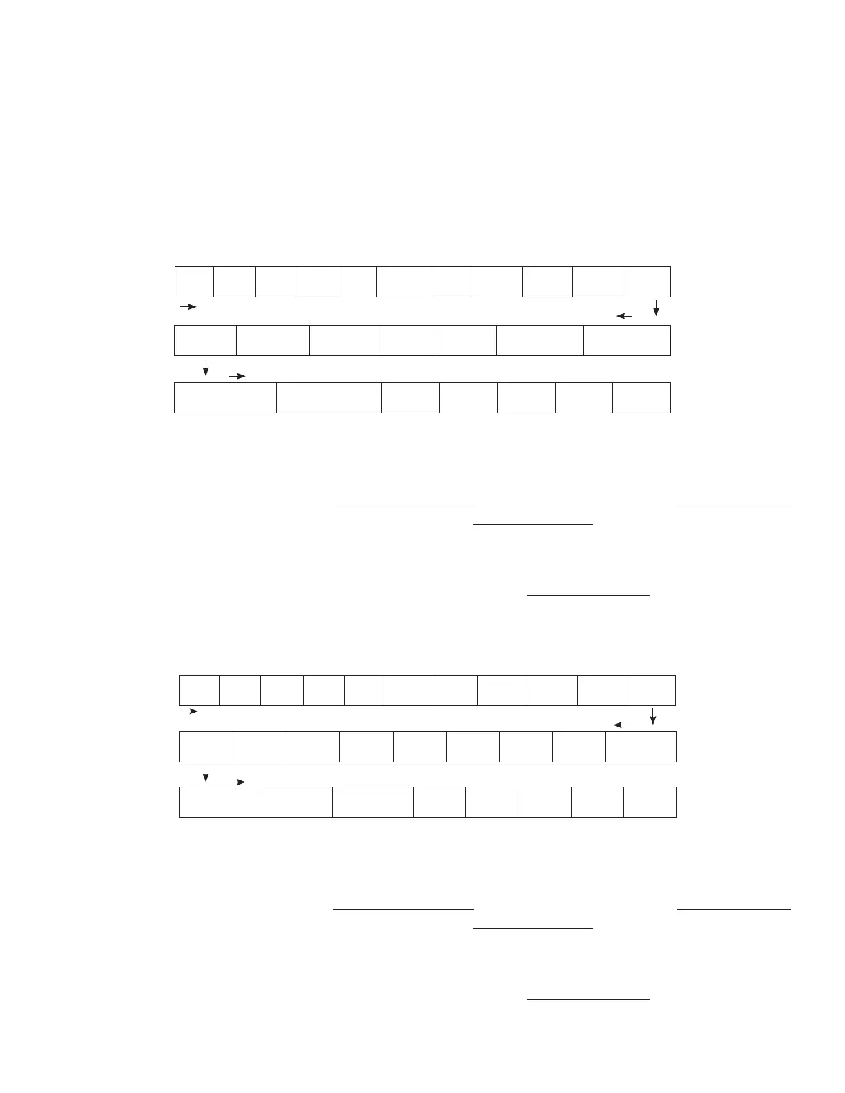
The following 25 Data Fields consisting of various electrical parameters, events and error codes are recorded for Models
EVO-1212F/1212F-HW/1224F/1224F-HW:
Date Time
Grid
status
Grid
freq
Grid
volt
Input
current
Input
VA
Inputt
watt
Output
freq
Output
Volt
Output
current
Output VA Output watt Battery volt
Battery
current
External
current
Battery
temperature (C)
Transformer
temperature (C)
Hear sink
temperature 1 (C)
Hear sink
temperature 2 (C)
Fan
speed
Mode
Error
code
Charge
stage
Event
Fig 5.1 Data Logging Fields for EVO-1212F/1212F-HW/1224F/1224F-HW
The Data Fields shown in Fig 5.1 above can be recorded at one of the 6 time interval options shown below under
programming parameter “DATALOG TIME” (See Section 4.8.2.10). Default time interval is 1 sec (Option “1=1 sec).
Parameter “DATALOG TIME” is also used to disable data logging (Option 0=Disable). Interval / disabling options are
shown below:
• 0=Disable ; 1=1 sec (Default) ; 2=10 sec ; 3=30 sec ; 4=60 sec ; 5=5 min ; 6=10 min
NOTE: The last data eld “Event” shown in Fig 5.1 above records an event as soon as it occurs
5.2.2.2 DATA LOGGING Fields for EVO-2212 / 3012 / 2224 / 4024
EVO-2212 / 3012 / 2224 / 4024 provides the following 28 Data Fields are shown in Fig 5.2 below:
Date Time
Gen
status
Gen
freq
Gen
volt
Grid
status
Grid
freq
Grid
volt
Input
current
Input
VA
Inputt
watt
Output
freq
Output
Volt
Output
current
Output
VA
Output
watt
Battery
volt
Battery
current
External
current
Battery
temperature
Transformer
temperature
Busbar
temperature
Heat sink
temperature
Fan
speed
Mode
Error
Code
Charge
stage
Event
Fig 5.1 Data Logging Fields for EVO-2212/ 3012/ 2224/ 4024
The Data Fields shown in Fig 5.2 above can be recorded at one of the 6 time interval options shown below under
programming parameter “DATALOG TIME” (See Section 4.8.2.10). Default time interval is 1 sec (Option “1=1 sec).
Parameter “DATALOG TIME” is also used to disable data logging (Option 0=Disable). Interval / disabling options are
shown below:
• 0=Disable ; 1=1 sec (Default) ; 2=10 sec ; 3=30 sec ; 4=60 sec ; 5=5 min ; 6=10 min
NOTE: The last data eld “Event” shown in Fig 5.2 above records an event as soon as it occurs
 Loading...