CHARGING STAGES
Note! - Voltage reading on no load. The output terminals of the charger consist of one
common white / black negative terminal (3) and two red positive terminals (1, 2) for
charging two banks of batteries. Each of the two positive terminals of the two banks has a
Schottky Diode in series for isolation. These isolating diodes have a current dependent
forward voltage drop ranging from 0.2 to 0.3 V (at 0.1 A) to 0.6 V (at 45 A). Please note
that the forward voltage drop occurs only when current flows through the diode. The
Float and Absorption voltages are tightly regulated before the isolating diodes. However,
the voltages available at the terminals of the two banks will vary with the value of the
charging current because of the current dependent forward voltage drop across the
isolating diodes. The Float and Boost / Absorption voltages before the diodes are,
therefore, set 0.2 to 0.3 V higher to compensate for the above forward drop during float
condition when the charging current would have dropped to less than 1 A. Hence, the
output voltage at the terminals of the two banks at no load (nothing connected to the
terminals of the banks) will read 0.2 to 0.3 V higher because there is no forward voltage
drop as there is no current flow through the diodes. Please also note that the output
voltage at the two banks may differ between 0.2 to 0.6 V depending upon the different
values of the charging current being delivered through each.
Page 9
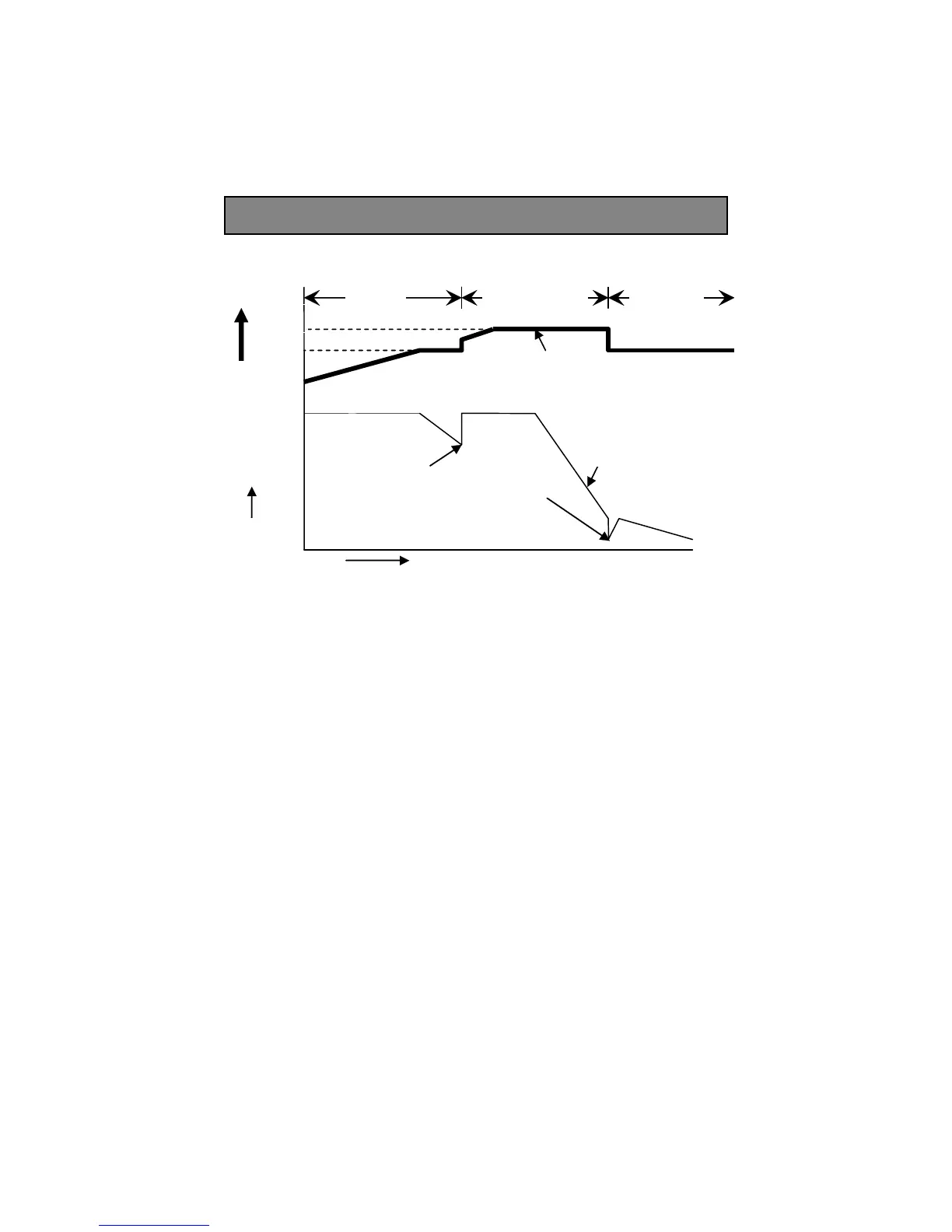
Stage 1
I Phase
Stage 2
Uo Phase
Timed for 4 / 8
Hours
Stage 3,
U Phase
Current, I
Voltage V
Time, Hours
Figure 1 Charging Curve
Curve for
Current I
Uo
U
80% of current
capacity of
charger
Curve for
Voltage U, Uo
10% of current
capacity of
charger