EasyManua.ls Logo

Samoa 536010 - User Manual

Samoa 536010
52 pages
Print Icon
To Next Page IconTo Next Page
Loading...
1
R. 03/23 853 801
SAMOA Industrial, S.A. · Pol. Ind. Porceyo, I-14 · Camino del Fontán, 831 · 33392 - Gijón - Spain · Tel.: +34 985 381 488 · www.samoaindustrial.com
2023_03_01-11:00
Parts and technical service guide
Guía de servicio técnico y recambio
Guide d’instructions et pièces de rechange
Service- und Ersatzteilhandbuch
Manual de Serviços Técnicos e Reposições
Список деталей и руководство по техническому обслуживанию
Part No. / Cód. / Réf. / Art. Nr. /
Cód. / Деталь №:
536010 536011
536030 536031
10:1 RATIO AIR OPERATED OIL PUMP PM45 2
BOMBA NEUMÁTICA DE ACEITE PM45, RATIO 10:1 8
POMPE PNEUMATIQUE D´HUILE PM45, RAPPORT DE PRESSION 10:1 14
DRUCKLUFTBETRIEBENE ÖLPUMPE PM45, ÜBERSETZUNG 10:1 20
PROPULSORA PNEUMÁTICA PARA ÓLEO PUMPMASTER 45, RATEIO 10:1 26
ПНЕВМАТИЧЕСКИЙ МАСЛЯНЫЙ НАСОС PM45, КОЭФФИЦИЕНТ СЖАТИЯ 10:1 32
EN
ES
FR
DE
PT
RU
!
ADVERTENCIA
LEA ATENTAMENTE EL MANUAL DE INSTRUCCIONES Y SUS
ADVERTENCIAS ANTES DE EMPEZAR A OPERAR CON EL EQUIPO
!
ADVERTÊNCIA
LER CUIDADOSAMENTE O MANUAL DE INSTRUÇÕES E OS SEUS
AVISOS ANTES DE COMEÇAR A OPERAR O EQUIPAMENTO.
!
WARNING
CAREFULLY READ USER MANUAL AND ITS WARNINGS
BEFORE USING THE PUMP
!
AVERTISSEMENT
LISEZ ATTENTIVEMENT LE MANUEL D’INSTRUCTIONS ET LES
AVERTISSEMENTS QU’IL CONTIENT AVANT DE COMMENCER
L’UTILISATION DE L’APPAREIL.
!
WARNUNG
LESEN SIE DIE BETRIEBSANLEITUNG UND DIE DARIN
ENTHALTENEN WARNHINWEISE SORGFÄLTIG DURCH, BEVOR SIE
DAS GERÄT IN BETRIEB NEHMEN
!
ВНИМАНИЕ
ВНИМАТЕЛЬНО ПРОЧИТАЙТЕ РУКОВОДСТВО
ПОЛЬЗОВАТЕЛЯ И ЕГО ПРЕДУПРЕЖДЕНИЯ ПЕРЕД
ИСПОЛЬЗОВАНИЕМ НАСОСА
Question and Answer IconNeed help?

Do you have a question about the Samoa 536010 and is the answer not in the manual?

Overview

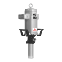
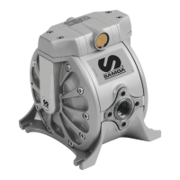
The SAMOA PM45 is a compressed air-powered reciprocating piston pump designed for professional use. It is suitable for handling mineral and synthetic oils in large installations with long piping, capable of supplying multiple fluid outlets simultaneously.

Technical Specifications:

The pump is available in two main models: 536030/536010 and 536031/536011, both with a 10:1 ratio.

  • Air Pressure:
    • Maximum: 12 bar (180 psi)
    • Minimum: 2 bar (29 psi)
    • Recommended: 6 bar (80 psi)
  • Maximum Delivery: 68 l/min @ 7 bar (18 gal/min @ 100 psi)
  • Air Inlet Thread:
    • 536030/536010: 1/2" BSP-F
    • 536031/536011: 1/2" NPT-F
  • Fluid Outlet Thread:
    • 536030/536010: 3/4" BSP-F
    • 536031/536011: 3/4" NPT-F
  • Air Piston Diameter: 115 mm (4.1/2")
  • Stroke: 100 mm (4")
  • Weight: 16.5 kg / 19 kg (36.4 lb / 42 lb) (varies by model)
  • Fluid Inlet Thread:
    • 536030/536010: 1-1/2" BSP-F
    • 536031/536011: 1-1/2" NPT-F
  • Ambient Temperature: -20°C ≤ Tamb ≤ 50°C
  • Maximum Surface Temperature: Dependent on oil temperature (never exceeding 70°C) or ambient temperature (whichever is greater).

Usage Features:

The PM45 pump is self-priming. For initial priming, connect the air supply and slowly increase the air pressure from 0 bar to the desired pressure using a pressure regulator. The pump begins to operate when an outlet valve, such as an oil control gun, is opened.

Installation:

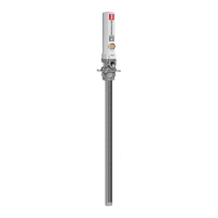
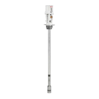
The pump can be installed in three ways:

  1. Wall Mounting: Using a wall-mounting bracket (Part No. 360132). Secure the bracket to the wall, then insert the pump through the bracket and fasten it with screws.
  2. Direct Drum or Tank Mounting: Screw the appropriate suction tube to the pump's foot valve. Insert the tube through the drum/tank cover and secure the pump to the cover with four M10 screws (112 mm center hole pattern diameter).
  3. Adjustable Drum or Tank Mounting: Using a bung adapter. Screw the appropriate suction tube to the pump's foot valve. Screw the bung adapter's nut to the 2" opening of the cover. Insert the suction tube through the nut and secure it at the desired height with a star nut.

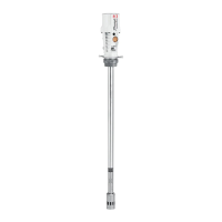
For ATEX compliance, the pump must be grounded using the included cable with a clamp (534907). These pumps are designed for direct installation on 200-liter drums by fixing them to the drum cover with four M10 screws.

ATEX Information:

The PM45 pump is suitable for use in potentially explosive atmospheres (ATEX). It complies with Directive 2014/34/EU and harmonized European norms (UNE-EN ISO 80079-36:2017). The ATEX marking is CE Ex II 2G Ex h IIB T4 Gb.

  • Ex: Indicates suitability for potentially explosive atmospheres.
  • h: Refers to standard 80079-36.
  • IIB: Equipment group for explosive gas atmospheres (excluding mines or hydrogen as the typical gas, Cat. 2G Zone 1).
  • T4: Temperature class for Group II (<= 135°C), considering maximum surface temperature when oil is 70°C (maximum allowable value) and several hours of dry running overheating.
  • Gb: Equipment Protection Level.
  • X: Indicates special conditions for safe use:
    • Ambient temperature: -20°C ≤ Tamb ≤ 50°C.
    • Maximum surface temperature depends on the oil being pumped (never exceeding 70°C) or ambient temperature (whichever is greater).
    • A grounding cable with a clamp is included and must be firmly and stably placed on a conductive element of the installation, external to the pump, and connected to the ground.

Zones of Use:

The pump is suitable for Zone 1 areas, where explosive atmospheres caused by mixtures of air with gases, vapors, or mists are likely to occur during normal operation.

Warnings and Cautions:

  • Equipment Misuse:
    • For professional use only.
    • Read all manuals, tags, and labels before operation.
    • Do not tamper with the equipment.
    • Use only for its intended purpose.
    • Install and use according to all local and national regulations, including health and safety laws.
    • Use only original replacement parts from Samoa Industrial, S.A.
    • Unauthorized modifications, misuse, improper maintenance, or removal of identification labels may void the warranty.
    • Disconnect from air supply when not in use to prevent accidents.
  • Chemical Compatibilities and Temperature Limits:
    • Do not use with fluids listed in section 1 of Pressure Equipment Directive 2014/34/EU (explosive, extremely flammable, highly flammable, flammable, highly toxic, toxic, oxidizing, or those with vapor pressure > 0.5 bar (7 psi) above atmospheric pressure at maximum allowable temperature).
    • Do not exceed maximum air inlet pressure of 12 bar (170 psi).
    • High pressures can cause serious injuries.
    • Release all stored pressure and disconnect from fluid systems before servicing. Service work must be done by qualified personnel.
    • All fittings in the system connected to the pump outlet must be suitable for the maximum pressure generated by the pump/air motor. Install safety or diverter valves if the system cannot withstand maximum pump pressure.
  • Safety Measures:
    • Ensure operators are trained on operation, product, and limitations.
    • Use required safety equipment.
    • Respect surface temperature considerations in explosive atmospheres as specified in the manual.

Maintenance Features:

Repair and Cleaning Procedure:

Before any maintenance or repair, disconnect the compressed air supply and open a downstream valve to relieve oil pressure. Apply grease to all seals during assembly.

Clean the Muffler (Fig. 5):

  1. Unscrew bolts (A).
  2. Remove exhaust assembly (B).
  3. Unscrew bolts (G) and remove cap (F).
  4. Remove felt (D).
  5. Remove felt (E) and deflector (C).
  6. Remove and replace bottom felt (D) with a new one.
  7. Replace deflector (C).
  8. Insert screws (A), then a new felt (E). (Order is important).
  9. Replace felt (D).
  10. Replace cap (F) and its screws (G).
  11. Ensure screws (A) stay in muffler (B), then place muffler on motor and fix with screws.
  12. A complete muffler assembly kit (SPARE PARTS KITS section) is available for replacement.

Air Distributor (Fig. 6):

  1. Unscrew bolts (H) and remove cap (G).
  2. Ensure screws (A) remain in muffler (B), unscrew them and remove the muffler. Remove o-ring (C).
  3. Gently strike with a plastic tool through the exhaust seat to remove spool valve (E).
  4. Replace seals (E) with new ones or replace the entire spool with factory-installed seals (SPARE PARTS KITS section) for correct assembly.

Air Motor Seals (Fig. 7):

  1. Unscrew bolts (A) and remove cap (B).
  2. Unscrew sensor sleeve (C).
  3. Using a manual clamp on nut (D), pull rod (O) outwards until its central recess appears. Then, with another manual clamp, grasp rod (O) at the recess to prevent sealing surface damage, and unscrew nut (D).
  4. Remove o-ring (E) and ring (F), and replace with new ones later.
  5. Unscrew bolts (R). Pull motor body (J) outwards with bridle (L).
  6. Remove gasket (G) and replace its seals (H) and (I).
  7. Unscrew bolts (M) and split motor (J) from bridle (L). Remove washer (K) and replace seal (H).
  8. Remove cylinder (N) while carefully holding air piston (Q). Replace piston seal (P).
  9. Reassemble in reverse order, applying thread locker to screws (M), nut (D), and sensor sleeve (C).
    • Note: All these seals are included in the available kit (SPARE PARTS KITS section).

Lower Seals Kit (Fig. 8):

For easier service, stop the pump near the lowest stroke position.

  1. Unscrew tube (K) from pump body (D).
  2. Unscrew piston (J) from rod (A). Remove ball (G) and washer (H). Replace V-ring (I).
  3. Unscrew bolts (E), remove outlet body (D), and replace seals (B, F) and guide ring (C).
  4. Reassemble in reverse order, applying thread locker to all joints.
    • Note: All these seals are included in the available kit (SPARE PARTS KITS section).

Troubleshooting:

The manual provides a detailed troubleshooting guide for common issues such as:

  • Pump not working or no oil delivery.
  • Pump operating too fast.
  • Pump continuing to operate when the oil outlet is closed.
  • Oil leakage through the air outlet muffler or leakage warning hole.
  • Air leakage through the air outlet muffler.
  • Low or diminishing oil output over time.

For each symptom, possible reasons and corresponding solutions are provided, ranging from increasing air supply pressure to cleaning or replacing specific components like seals, O-rings, or muffler felt.

Samoa 536010 Specifications

General IconGeneral
BrandSamoa
Model536010
CategoryWater Pump
LanguageEnglish

Related product manuals