18
855 821 R. 02/17
SAMOA Industrial, S.A. · Pol. Ind. Porceyo, I-14 · Camino del Fontán, 831 · 33392 - Gijón - Spain · Tel.: +34 985 381 488 · www.samoaindustrial.com
2017_02_01-13:00
Repair and maintenance procedures
Torques necessary for the proper functioning of the pump
For proper operation of the pump and to prevent accidents which may damage equipment and in the worst case, people, you must periodically review
the torques of the diaphragms covers and the DIRECTIONAL VALVE. In the next table are shown the appropriate torques for this purpose:
Torques DF50
Diaphragm cover 48.67 - 53.1 lbf·in (5,5 - 6 N·m)
Directional valve 44.25 lbf·in (5N·m)
Valve cap 35.4 lbf·in (4 N·m) Aluminium - 30.9 lbf·in (2 N·m) composite
Diaphragm replacement
Torques DF30
Diaphragm cover 70.81 lbf·in (8 N·m)
Directional valve 44.25 lbf·in (5 N·m)
Valve cap 30.9 lbf·in (2 N·m) composite
Torques DF100
Diaphragm cover 137.7 lbf·in (15 N·m)
Directional valve 44.25 lbf·in (5 N·m)
Valve cap 35.4 lbf·in (4 N·m) Aluminium - 30.9 lbf·in (2 N·m) composite
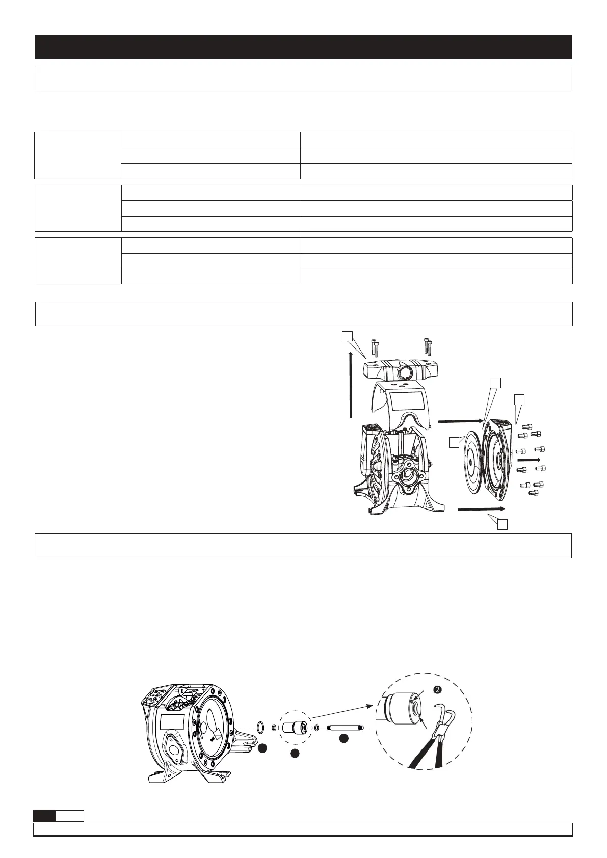
Before any intervention: DISCONNECT AIR SUPPLY OF THE PUMP.
IT IS NOT NECESSARY TO REMOVE THE PUMP FROM THE FLUID LINE.
1. Close fluid valves.
2. Drain the fluid inside the pump. Anticipate a drainage of fluid from inside
the pump.
3. Remove the directional valve while being careful not to damage the
seals shown in the figure.
4. Remove the diaphragm cap.
NOTE: To tighten these screws you must use a torque wrench
calibrated to (see torque table in this page).
5. Remove the cover by gently pulling back.
6. Remove the used diaphragm and place the new one in the proper
position.
Assemble components.
4
A
6
5
3
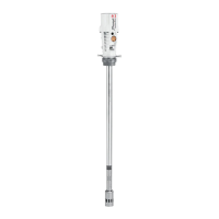
Pushing rod
Remove the side cover on the right of the fluid inlet as shown in the
figure, following the procedure to “Replace diaphragms".
Once the shaft is visible, use the following procedures:
1. Remove the shaft from its housing by pulling it from one end.
The Teflon
®
sleeve is threaded into the body. To remove use snap ring
pliers in the two holes indicated in the figure.
2. Once the cap has been removed, remove the quad ring inside the
pump body.
3. Replace the kit following the correct order shown in the assembly
drawing.
Reassemble the pump in reverse order.
2
1
3