20 | SAMLEX AMERICA INC.
6.1 LAYOUT
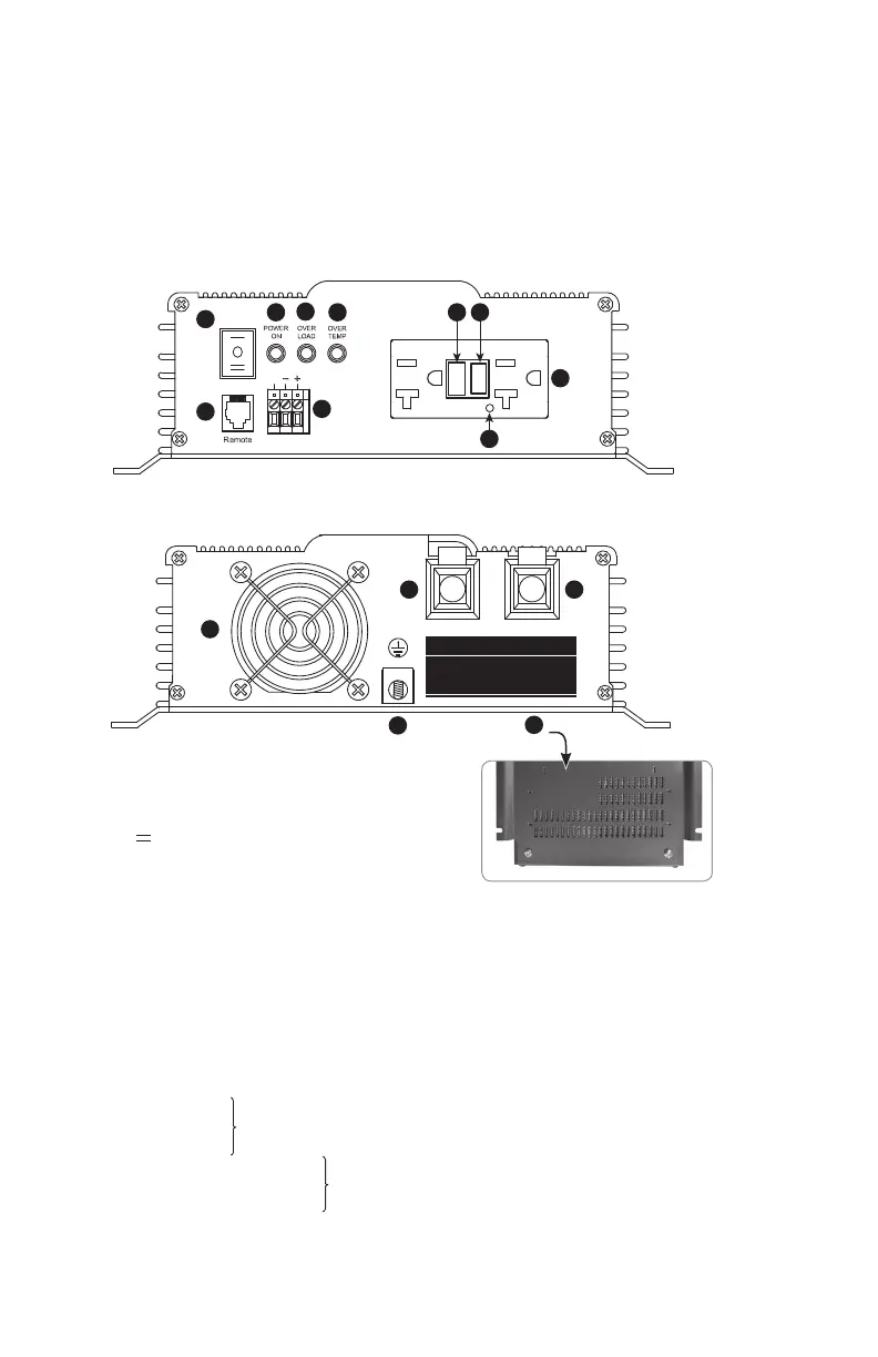
Layout of the unit is shown in Fig 6.1 below
Fig. 6.1: Layout of PST-600-12 & PST-600-24
Legend
1. Three Position Rocker Switch
• — ON − Push top end to switch ON locally
• 0 OFF − Center to switch OFF locally
• EXT Switch − Push bottom end to enable
switching ON and OFF by external
1-Wire / 2-Wire switching control
(Refer to Section 8.9)
2. Green LED - Power ON
3. Red LED - Overload
4. Red LED - Over Temperature
4A. Hardwiring Terminal Block marked EXT.SW. for ON/OFF switching using external control signals
5. NEMA5-20R Self Monitoring GFCI Duplex Outlets (Refer to Section 8.5.2)
5A. Reset Button
5B. Test Button
5C. Dual Color (Green/Red) Status LED for GFCI
6A. Ventilation slots at the bottom for air suction for cooling fan
6B. Cooling Fan Opening for air discharge
7. Grounding Lug: Wire hole diameter: 5/16”
Set screw: • 5/16” x 24 TPI
• 3/8” long ; Slotted Head
8. Negative (-) DC Input Terminal
9. Positive (+) DC Input Terminal
10. Modular Jack (6P6C) for RC-15A Remote Control (optional)
1
10
PST-600-12/PST-600-24 (Front)
PST-600-12/PST-600-24 (Back)
2
3
4
4A
ON
OFF
EXT.
S
EXT.SW.
TEST MONTHLY
TEST MENSUET
FOLLOW DIRECTIONS
SUIVEZ INSTRUCTION
5A 5B
5
5C
120 VAC / 60Hz
600W POWER INVERTER
6B
7
8 9
6A
Wire hole diameter: 7/16”
Set screw: • 5/16” x 24 TPI
• 1/2” long ; Slotted Head
RESET
RESET
TEST
TEST
NEG –
WARNING:
Reverse polarity will damage the unit.
AVERTISSEMENT :
Inversion de polarité peut endommager l’unité.
NEG – POS +
SECTION 6 | Layout