3-2 EB 8052 EN
Design and principle of operation
1 Body
2 Bonnet
3 Yoke
4 Seat
5 Plug (with plug stem)
8 Threaded bushing (pack-
ing nut)
9 Stem connector nut
10 Lock nut
14 Nut
15 Packing
17 Body gasket
84 Travel indicator scale
92 Castellated nut
A Actuator
A4 Diaphragm
A7 Actuator stem
A8 Ring nut
A10 Spring
A16 Vent plug
A26 Stem connector clamps
S Signal pressure connec-
tion
A10
A4
S
A7
84
A26
9
10
8
92
3
2
5
4
A
A8
15
14
17
1
S
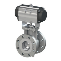
Fig.3-1: Type3251/3251-AM Valve with Type3271 Pneumatic Actuator (left) and Type3277
Pneumatic Actuator (right)