6
C com opti Layout
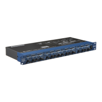
AACINLET - AC Power Supply Connector.
B STEREO LINK INPUT- 1/4” TRS Connector for
linking two C com opti’s together for stereo
operation.
C 1/4” TRS OUTPUT - 1/4” TRS connector for
Balanced line OUTPUT.
D 1/4” TRS INPUT - 1/4” TRS connector for
Balanced line INPUT.
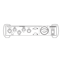
1 THRESHOLD - Used to set the minimum signal level
at which the compressor circuit begins to function.
2 RATIO - Controls the amount of gain reduction in
proportion to the amount of signal over the select-
ed threshold level.
3 RELEASE - Adjusts the length of time the compres-
sor takes to return the signal to it’s original level.
4 METER SWITCH - When pressed in, the METER
shows OUTPUT level and in the out position the
METER shows GAIN REDUCTION.
5 VU METER - Back-lit, analog VU meter which,
depending on the METER switch, displays the
amount of Gain Reduction or Output Level.
6 MAINS POWER SWITCH - When pressed on,
the green LED lights indicating that the C com
opti is powered up and ready for operation.
7 ENHANCE SWITCH - Used to engage the C
com opti’s Enhance circuit restoring the high
end loss resulting from extreme Gain
Reduction.
8 ATTACK - Adjusts the amount of time the com-
pressor takes to reach full gain reduction.
9 OUTPUT - Controls the overall level, and is
used for “make-up” gain to restore the signal
back to its original level after the compression.
10 BYPASS SWITCH- When pressed in, the green
LED lights indicating that the C com opti’s com-
pression circuit is active.