Do you have a question about the Samson S-Gate 4 and is the answer not in the manual?
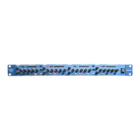
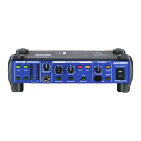
Detailed diagram and explanation of the front panel controls and indicators.
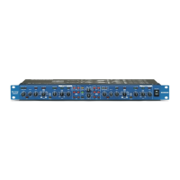
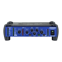
Detailed diagram and explanation of the rear panel connectors and controls.
Connect inputs/outputs and set initial controls for basic operation.
Step-by-step guide to removing unwanted noise using the gate function.
Utilize the DFT circuit for frequency-specific gate triggering.
Configure the Ducker to automatically mix sound sources based on a key signal.
Overview of compressor parameters like threshold, ratio, attack, and release.
Explanation of automatic knee detection for smoother gain changes.
How noise gates work to remove unwanted noise and bleed.
Purpose of a downward expander to increase perceived dynamic range.
Definition of a limiter for peak prevention and overload protection.
How to configure dual-mono to stereo operation using the Stereo Link switch.
Techniques for reducing unwanted noise and cross-talk with the gate.
Using noise gates effectively on drum microphones in live and studio settings.
Adjusting release time for sounds with longer decay, like pianos.
Making rhythm sections tighter and cleaning up tracks with gating.
Wiring diagram for inserting gates on individual mixer channels.
Wiring diagram for connecting gates to mixer sub insert points.
Using channel and bus insert points for connecting the S gate 4.
Installing the S gate 4 in-line between mixer and amplifier/equalizer.
Wiring example for unbalanced 1/4" connectors.
Wiring example for balanced XLR connectors.
Pinout details for XLR and 1/4" connections.
Technical specifications including frequency response, dynamic range, THD, and crosstalk.
Detailed gate parameters: trigger range, attack, release, hold, and range.
Ducker range specifications.
Description of Link, Filter, Key Listen, Ducker, and In/Out switch functions.
Details on Gain Reduction and Gate Activity LED displays.
Connectors, impedance, and input levels.
Connectors, impedance, and output levels.
Mains voltages, fuse, power consumption, and inlet type.
Physical dimensions and weight of the unit.
| Brand | Samson |
|---|---|
| Model | S-Gate 4 |
| Category | Recording Equipment |
| Language | English |