15
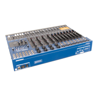
XM410 System Set-Ups
3)'.!,&,/7
3)'.!,&,/7
3)'.!,&,/7
3)'.!,&,/7
3
!
-
3
/
.
2
3
!
-
3
/
.
2
3)'.!,&,/7
3)'.!,&,/7
SAMSON TECHNOLOGIES CORP., HICKSVILLE, NEW YORK
TO PRE VENT SH OCK DO
NOT OPE N . N O USE R
SER V IC A B LE PAR TS
INSIDE. REFER SERVICING
TO QU ALI FIE D SER VIC E
PERSONNEL. TO PREVENT
FIRE OR SH OCK HAZARD
DO NOT EXPOSE TO RAIN
OR MOISTURE.
CAUTION
HEATSINK MAY BE
HOT! DO NOT BLOCK
AIRFLOW OR OVER-
HEATING MAY OCCUR
RISK OF ELECTRIC SHOCK
DO NOT OPEN
SERIAL
NUMBER
FUSE
FUSE RATING
12A/250V (115V)
6A/250V (230V)
CAUTION
!
~AC INPUT
115V/230W, 50/60HZ
510W (115V)900W (230V)
USE CLASS 2 WIRING MAXIMUM LOAD IMPEDANCE 47
RIGHT
LEFT
+RIGHT
LEFT+
GROUND
OUTPUT 250W/47
SERVO 550 STUDIO AMPLIFIER
RIGHT
LEFT
BRIDGED
MONO STEREO
INPUTS
(BALANCED
10K7/0dBm0)
TIP RING SLEEVE
TIP +
RING -
SLEEVE GND
This system shows the
XM410 power amp
operating in MAIN/MAIN
mode, with one speaker
connected to POWER
AMP 1 and one speaker
connected to POWER
AMP 2. The MONITOR
OUT is connected to an
external power amp,
which is driving 2 moni-
tor speakers. For inputs,
two microphones are
connected to channel
1 and 2’s low-imped-
ance inputs, and the
output of the Bass Direct
Box is also connected
to the Low-Impedance
input on channel 4. The
Keyboards, as well as
the Lead and Rhythm
Guitar signal processors’
outputs, are connected to
the XM410’s line inputs.
XM410’s MONITOR OUT
connected to an external
monitor amp.