This document is an installation manual for a Samsung Air Conditioner, specifically models AC**BNDCH. It provides comprehensive instructions for the installation, setup, and basic troubleshooting of the indoor unit.
Function Description
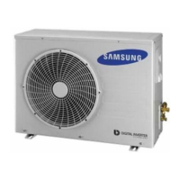
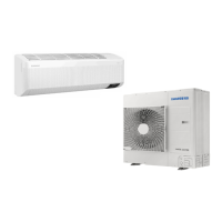
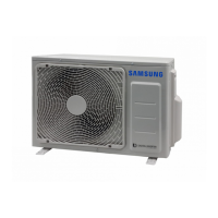
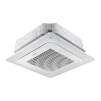
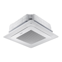
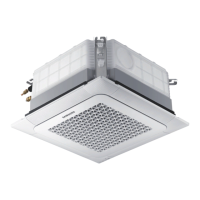
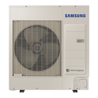
The Samsung Air Conditioner is designed for cooling and heating applications in various indoor environments. It operates as a split system, requiring both an indoor and an outdoor unit. The manual focuses on the indoor unit's installation, including its physical placement, refrigerant piping, drainage, and electrical connections. The unit supports both free-air discharge and connection to a duct system for air distribution. Advanced features include an Automatic Air-Volume function for smart fan speed adjustment based on installation conditions and an Emergency Temperature Output (ETO) function for multi-system emergency operation. The system can be controlled via a wired remote controller, which also allows for setting various installation options and addresses.
Important Technical Specifications
The manual provides detailed dimensions and connection specifications for different indoor unit models:
- AC009BNLDCH/AC012BNLDCH:
- Unit dimensions: 35.43 x 17.32 x 7.83 inches (900 x 440 x 199 mm)
- Liquid pipe connection: Ø1/4 inch (6.35 mm)
- Gas pipe connection: Ø3/8 inch (9.52 mm)
- Drain pipe connection: 3/4 inch (OD 1.05 inch (26.67 mm))
- Suspension position: 37.21 inches (945 mm)
- AC018BNLDCH:
- Unit dimensions: 43.31 x 17.32 x 7.83 inches (1100 x 440 x 199 mm)
- Liquid pipe connection: Ø1/4 inch (6.35 mm)
- Gas pipe connection: Ø1/2 inch (12.70 mm)
- Drain pipe connection: 3/4 inch (OD 1.05 inch (26.67 mm))
- Suspension position: 45.08 inches (1145 mm)
- AC009BNHDCH/AC012BNHDCH:
- Unit dimensions: 33.46 x 27.56 x 9.84 inches (850 x 700 x 250 mm)
- Liquid pipe connection: Ø1/4 inch (6.35 mm)
- Gas pipe connection: Ø3/8 inch (9.52 mm)
- Drain pipe connection: 3/4 inch (OD 1.05 inch (26.67 mm))
- Suspension position: 35.43 inches (900 mm)
- AC018BNHDCH/AC024BNHDCH/AC030BNHDCH:
- Unit dimensions: 47.24 x 27.56 x 9.84 inches (1200 x 700 x 250 mm)
- Liquid pipe connection: Ø1/4 inch (6.35 mm)
- Gas pipe connection: Ø1/2 inch (12.70 mm) (for AC018BNHDCH/AC024BNHDCH)
- Gas pipe connection: Ø5/8 inch (15.88 mm) (for AC030BNHDCH)
- Drain pipe connection: 3/4 inch (OD 1.05 inch (26.67 mm))
- Suspension position: 49.21 inches (1250 mm)
- AC036BNHDCH/AC042BNHDCH/AC048BNHDCH:
- Unit dimensions: 51.18 x 27.56 x 11.81 inches (1300 x 700 x 300 mm)
- Liquid pipe connection: Ø3/8 inch (9.52 mm)
- Gas pipe connection: Ø5/8 inch (15.88 mm)
- Drain pipe connection: 3/4 inch (OD 1.05 inch (26.67 mm))
- Suspension position: 53.15 inches (1350 mm)
Refrigerant Piping:
- Copper pipe must be insulated, unwelded, degreased, and deoxidized (Cu DHP type to ISO 1337 or UNI EN 12735-1).
- Suitable for operating pressures of at least 4200kPa and burst pressure of at least 20700kPa.
- Flare dimensions and tightening torques are specified for various pipe diameters (Ø1/4" to Ø3/4").
- Nitrogen blowing pressure range for brazing: 0.02 ~ 0.05MPa.
- Insulation thickness recommendations vary based on humidity conditions (General: 9-13mm, High humidity: 9-19mm for liquid pipe; General: 13-25mm, High humidity: 19-38mm for gas pipe). Heat-resistance temperature of insulator must be more than 248°F (120°C).
Electrical Connections:
- Power supply: 208 to 230V, 60 Hz, ±10%.
- Indoor power cable: 0.0023 inch² (1.5mm²), 3 wires.
- Communication cable: 0.0012 inch² (0.75mm²), 2 wires.
- Power supply cords for outdoor units must be polychloroprene sheathed flexible cord (H05RN-F grade or more).
- Tightening torques for M3.5 screws (0.58 to 0.87 lbf·ft) and M4 screws (0.87 to 1.30 lbf·ft) are provided.
- Double shielded communication cable (tape aluminum / polyester braid + copper) of FROHH2R type is recommended for computer or server rooms.
Usage Features
- Wired Remote Control: The primary interface for controlling the air conditioner and setting advanced functions. It allows access to Main Menu and Sub-menu settings.
- Automatic Air-Volume Function: Automatically adjusts indoor unit fan speed based on external static pressure and installation conditions to maintain rated volume flow rate. Not available for AC***BNLDCH models.
- External Static Pressure (ESP) Setting: Allows manual adjustment of fan speed for phase control motors by inputting specific option codes, optimizing performance for different duct lengths and static pressures.
- Emergency Temperature Output (ETO) Function: In multi-system configurations, if a main indoor unit stops due to an error, a sub indoor unit can automatically start operating in a predefined mode (default 24°C/75°F Auto mode for first operation). This requires an external contact interface module (MIM-B14) for each indoor unit.
- EASY Tuning: Allows users to adjust airflow rates for cooling and heating modes, or to prioritize silent operation, with +2 to -2 steps of adjustment.
- Indoor Unit Address and Installation Options: Configurable via the wired remote controller, allowing for unique addressing in multi-unit systems and setting various installation-specific parameters.
- Wireless Remote Control: Provides an alternative method for setting indoor unit addresses and installation options, particularly useful during initial setup.
Maintenance Features
- Gas Leak Test: Essential procedure using high-pressure nitrogen (above 580.2 psi/4 Mpa) to detect refrigerant leaks before vacuuming and charging the system.
- Drainage Test: Involves pouring water into the indoor unit to confirm proper drainage and check for leaks, ensuring the drain hose and pipe are functioning correctly.
- Accessible Connections: All refrigerant connections must be accessible for easy maintenance and detachment.
- Insulation Integrity: Instructions emphasize proper insulation of refrigerant pipes and drain hoses to prevent condensation and maintain efficiency. Regular inspection for cracks or waves in insulation is implied.
- Troubleshooting Indicators: The manual includes a detailed table of abnormal conditions indicated by LED flickers on the unit and error codes displayed on the wired remote controller, aiding in quick diagnosis of issues such as communication errors, sensor failures, fan motor problems, and more.
- Filter Usage Time: An option (SEG18) to set the maximum filter usage time, which can be configured for 1000 or 2000 hours, indicating when filter maintenance might be needed.
- Buzzer Control: An option (SEG17) to enable or disable the buzzer, which can be useful during maintenance or in specific environments.
- Heating Setting Compensation: An option (SEG21) to adjust heating settings by 3.6°F (2°C) or 9°F (5°C), with a default of 3.6°F (2°C).