Installation
2)1&U-,0&1&,+
Selecting the installation location
Decide the installation location, with the consideration of the following conditions, under user’s approval.
࡛ ťɇʀʪи˵ʪθʪɇθѤͱиϑͱϩʒϑϩЇθɵʪʒ
࡛ ťɇʀʪͱѤɇϩϑЇθ˙ɇʀʪи˵ʪθʪϩ˵ʪϑϩθЇʀϩЇθʪʀɇɵʪɇθϩ˵ʪиʪ˝˵ϩɇʒЭɵθɇϩͱͱ˙ϩ˵ʪʒͱͱθЇϩ࣑Ã˙ϩ˵ʪϑϩθЇʀϩЇθʪϑͱϩ
ϑϩθͱ˝ʪͱЇ˝˵ࡥʒͱͱθЇϩɇц˙ɇɇʒɵʪʒɇɇ˝ʪʒͱθʀɇЇϑʪΧʪθϑͱɇЇθц࣒
࡛ ťɇʀʪи˵ʪθʪϑЇ˙ѣʀʪϩϑΧɇʀʪʀɇɵʪ˝Їɇθɇϩʪʪʒ˙ͱθɇϩʪɇʀʪɇʒͱϩ˵ʪθϑʪθЭʀʪϑ
࡛ Place where condensation can be drained easily.
࡛ Place that allows refrigerant pipe connection within allowable distance.
࡛ Place where indoor unit will not be exposed to direct sunlight.
࡛ Place that can keep the distance of at least 3.28 ft (1 m) between power/communication cable and any electronic
devices (depending on the circumstances, problem may occur even if you secure 3.28 ft (1 m) of distance).
Refrigerant pipe work must be done before installing the indoor unit.
Location
Access for servicing is an important factor in the location of any air handler. Provide a minimum of 30 inches in front of the
ɇΧΧɇʀʪ˙ͱθɇʀʀʪϑϑϩͱϩ˵ʪʀͱϩθͱɵͱуࡥ˵ʪɇϩ˝ʪʪʪϩϑࡥɵͱиʪθɇʒɇθѣϩʪθϑƟ˵ϑɇʀʀʪϑϑɇцɵʪΧθͱЭʒʪʒɵцɇʀͱϑʪϩ
door or by locating the appliance so that a wall or partition is not less than 30 inches from the front access panel. Location
ϑЇϑЇɇцΧθʪʒʪϩʪθʪʒŵʪ˙ʪθϩͱѣ˝ЇθʪɵʪͱиA˵ʪʀиϩ˵ͱиʪθࣱϑͱθʒʪɇʪθࣱϑϑϩɇɇϩͱΧɇϑÃ˙ͱʀɇϩͱ˵ɇϑͱϩɵʪʪ
decided, consider the following in choosing a suitable location.
1. Select a location with adequate structural support, space for service access, and clearance for return and supply duct
connections.
2. ĘͱθɇͱΧʪθɇϩ˝ϑͱЇʒʪЭʪϑɇцɵʪͱɵʪʀϩͱɇɵʪ˙ϩ˵ʪɇθ˵ɇʒʪθϑΧɇʀʪʒʒθʪʀϩцͱЭʪθͱθЇʒʪθϑͱʪθͱͱϑϑЇʀ˵ɇϑ
bedrooms, study, etc.
3. Caution should be taken to locate the unit so that supply and return air ducts are about the same length causing even air
distribution of supply and return air to and from the living spaces.
4. Locate appliance where electrical supply wiring can be easily routed to main electrical panel and where electrical wiring will
not be damaged.
5. Locate appliance where control wiring can be easily routed to the controller and where the wiring will not be damaged.
6. Locate appliance where refrigerant lines can be easily routed from the evaporator coil to the system.
7. Locate the appliance where condensate lines can be easily routed to an available drain. Be sure to route condensate drain
ΧΧ˝ϑͱɇϑͱϩϩͱͱɵϑϩθЇʀϩɇʀʀʪϑϑϩͱϩ˵ʪɇθѣϩʪθ
8. The coil is installed in a draw-thru application and will create a negative pressure situation in the condensate drain system.
To prevent condensate from being drawn into the blower it is recommended to trap the primary (Main) and secondary
࣑ĮЭʪθѤͱи࣒ʒθɇʪŵʪ˙ʪθϩͱUθɇťΧʪɇʒUθɇ²ͱϑʪϑʪʀϩͱϩ˵ʪϑʪϑϩθЇʀϩͱϑÃ˙ϩ˵ʪϑʪʀͱʒɇθцʒθɇϑͱϩЇϑʪʒࡥ
it must be capped. This unit has a connection terminal for drain system monitoring. Refer to Wiring Work section for
˙ͱθɇϩͱθʪ˝ɇθʒ˝ʀͱʪʀϩͱͱ˙ѣʪʒࣛΧθͱЭʒʪʒʀͱʒʪϑɇϩʪͱЭʪθѤͱиʒʪЭʀʪϑϩ˵ʪϑʪϑϩθЇʀϩͱϑ
9. The draw-thru design will cause exterior surface of cabinet to sweat when unit is installed in a non-conditioned space
such as an attic or garage. Installer must provide protection such as full size auxiliary drain pan on all units installed in a
non-conditioned space to prevent damage from condensation runoff. Some states, cities and counties require additional
insulation to be installed on the exterior casing of the air handler to prevent sweating. Refer to the state, city, county or local
code for insulation requirement to be sure the installation is in compliance. It is recommended that air handlers installed in
non-conditioned spaces be insulated on the exterior of the entire cabinet, including the front access panel with one (1) inch
ϩ˵ʀѣɵʪθ˝ɇϑϑиϩ˵ϩ˵ʪЭɇΧͱθɵɇθθʪθͱϩ˵ʪͱЇϩϑʒʪ
10. kϑЇθʪϑЇ˙ѣʀʪϩϑΧɇʀʪ˙ͱθϩ˵ʪɵͱϩϩͱͱ˙ϩ˵ʪΧθͱʒЇʀϩ࣑²ʒʪϑͱ࣒ϑͱϩ˵ɇϩɇʒͱииɇθʒϑͱΧʪͱ˙ߣࢩߣߢߢʀɇɵʪɇϩɇʪʒ˙ͱθ
drain piping, as described for the intake duct installation and in “Drain pipe installation”.
H
H
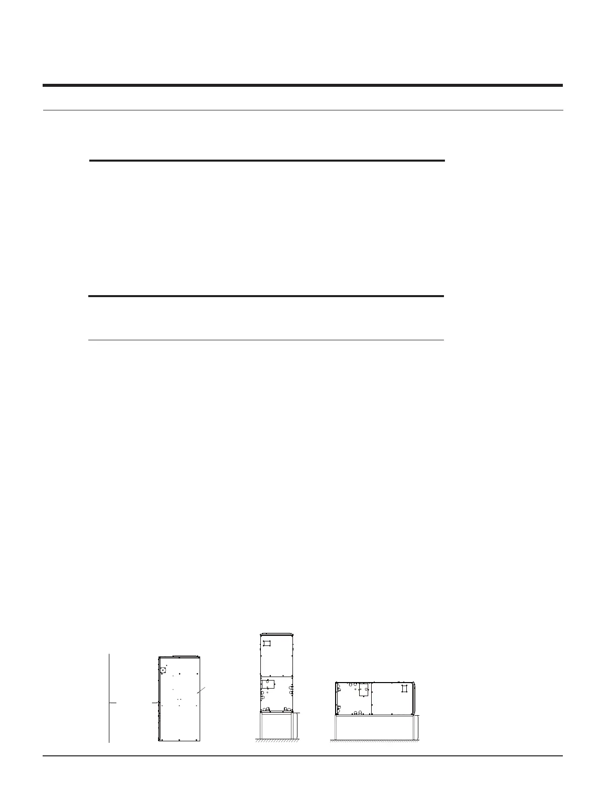
Clearance - Access for service
30" minimum
Right side of unit
Vertical installation Horizontal installation
Indoor unit installation
 Loading...