EasyManua.ls Logo

Samsung AC042JXADCH/AA User Manual

Samsung AC042JXADCH/AA
101 pages
To Next Page IconTo Next Page
Page #1 background imageLoading...
Page #1 background image
AIR CONDITIONER CONTENTS
SYSTEM AIR CONDITIONER
4 WAY CASSETTE SERIES
1. Precautions
2. Product Specifications
3. Disassembly and Reassembly
4. Troubleshooting
5. PCB Diagram
6. Wiring Diagram
7. Reference Sheet
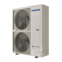
INDOOR UNIT OUTDOOR UNIT
Model :
AC018JN4DCH/AA
AC024JN4DCH/AA
AC030JN4DCH/AA
AC036JN4DCH/AA
AC042JN4DCH/AA
AC048JN4DCH/AA
AC024KN4DCH/CB
AC036KN4DCH/CB
AC018JXADCH/AA
AC024JXADCH/AA
AC030JXADCH/AA
AC036JXADCH/AA
AC042JXADCH/AA
AC048JXADCH/AA
AC024KXAPCH/CB
AC036KXAPCH/CB

Questions and Answers:

Samsung AC042JXADCH/AA Specifications

General IconGeneral
Cooling Capacity4.2 kW
Power Source220-240V, 50Hz
RefrigerantR410A
Energy Efficiency Ratio (EER)3.2
Weight (Indoor Unit)9 kg

Summary

Precautions

1-1 Precautions for the Service

Guidelines for safe and effective service procedures.

1-2 Precautions related to static electricity and PL

Warnings about static electricity and Product Liability.

1-3 Precautions related to product safety

Essential safety measures to prevent hazards during operation.

1-4 Other precautions

Additional important precautions for installation and operation.

Product Specifications

2-1 The Feature of Product

Highlights the key features and benefits of the air conditioner.

2-2 Product Specifications

Detailed technical specifications including performance and dimensions.

2-3 Specifications of optional items

Lists and details optional accessories for the air conditioner.

2-3-2 Filter specifications

Details specifications for the unit's filter.

Disassembly and Reassembly

Necessary Tools

Lists essential tools required for disassembly and reassembly.

3-1 Indoor unit

Step-by-step guide for disassembling the indoor unit.

3-2 Outdoor Unit

Step-by-step guide for disassembling the outdoor unit.

Troubleshooting

4-1 Setting an indoor unit address and installation option

How to set unit address and installation options via remote.

4-1-3 Order for Setting Options (Wired Remote Controller)

Sequence for setting options using a wired remote controller.

4-1-5 Changing a particular option

How to modify individual setting digits for options.

4-1-6 Option code for each model

Reference table for model-specific option codes.

4-2 Items to check before diagnostics

Preliminary checks before performing diagnostics.

4-2-1 Test run mode and View mode

Procedures for test run and viewing system status.

4-2-2 Eco Mode [Power Saving Mode]

Explanation and operation of the energy-saving Eco Mode.

4-2-3 Four directions cassette type

Troubleshooting specific to four-direction cassette models.

4-2-4 Wired remote controller

Troubleshooting common errors related to the wired remote controller.

4-3 Troubleshooting by symptoms

Diagnosing issues based on observed symptoms.

4-3-1 Indoor temperature sensor (open/short)

Diagnosing indoor temperature sensor faults.

4-3-2 Indoor heat exchanger temperature sensor (open/short)

Diagnosing heat exchanger sensor faults.

4-3-3 Indoor FAN error

Troubleshooting problems with the indoor unit fan.

4-3-4 Communication error after finishing Tracking

Resolving communication errors after initial setup.

4-3-5 Indoor unit float sensor error

Diagnosing issues related to the indoor unit's float sensor.

4-3-6 EEPROM circuit failure

Troubleshooting EEPROM circuit failures.

4-3-7 Thermal Fuse Open Error

Diagnosing and resolving thermal fuse open errors.

4-3-8 When the outdoor unit power is not ON – Initial Diagnosis : 3-phase products

Initial diagnosis for 3-phase products with no outdoor unit power.

4-3-8 When the outdoor unit power is not ON – Initial Diagnosis : Single-phase product

Initial diagnosis for single-phase products with no outdoor unit power.

4-3-9 Indoor/outdoor communication error (1min.) (Error Code: E202)

Troubleshooting indoor/outdoor communication errors (1 min).

4-3-12 Outdoor Unit Fan Error (Error Code: E458, E475)

Diagnosing and resolving outdoor unit fan errors.

4-3-13 Error of Compressor Startup and Rotation (Error Code: E461, E467)

Troubleshooting compressor startup and rotation issues.

4-3-15 IPM Over-current Error (Error Code: E464)

Troubleshooting IPM over-current errors.

4-3-16 DC LINK Over-current and Low-voltage Error (Error Code: E466)

Resolving DC link over-current and low-voltage errors.

4-3-17 Gas Leakage Error (Error Code: E554)

Diagnosing and resolving gas leakage errors.

4-3-18 Pipe Blocking Error (Error Code: E422)

Troubleshooting pipe blocking errors.

4-3-19 Other

Addresses miscellaneous troubleshooting issues and error codes.

PCB Diagram and Parts List

5-1 Indoor Unit

PCB diagrams and parts list for the indoor unit.

5-1-1 MAIN PCB

Detailed diagram and parts for the indoor unit's main PCB.

5-1-2 Panel PCB

Diagram and parts for the indoor unit's panel PCB.

5-2 Outdoor Unit

PCB diagrams and parts list for the outdoor unit.

5-2-1 Main PCB

Diagram and parts for the outdoor unit's main PCB.

5-2-2 SUB PCB

Diagram and parts for the outdoor unit's sub PCB.

5-2-3 SMPS

Diagram and parts for the outdoor unit's SMPS.

5-2-4 MAIN PCB

Diagram and parts for the outdoor unit's main PCB (different models).

5-2-5 INVERTER PCB

Diagram and parts for the outdoor unit's inverter PCB.

5-2-6 EMI PCB

Diagram and parts for the outdoor unit's EMI PCB.

Wiring Diagram

6-1 Indoor Unit

Wiring diagram for the indoor unit.

6-2 Outdoor unit

Wiring diagram for the outdoor unit.

Reference Sheet

7-1 Index for Model Name

Index to understand model name codes.

7-1-1 Indoor Unit

Guide to decode Indoor Unit model names.

7-1-2 Outdoor Unit

Guide to decode Outdoor Unit model names.

7-1-3 Panel

Guide to decode Panel model names.

7-2 Refrigerating Cycle Diagram

Diagram illustrating the air conditioner's refrigeration cycle.

Related product manuals