24
Installation Procedure
English
Installation Procedure
Please fill in the following with indelible ink on the
refrigerant charge label supplied with this product and
on this manual.
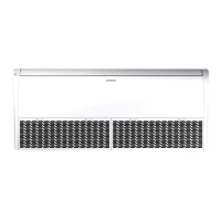
•
: The factory refrigerant charge of the product.
•
:
The additional refrigerant amount charged in the field.
• + : The total refrigerant charge.
2
1
Indoor Unit
Outdoor Unit
Unit kg tCOe
, a
, b
+ , c
Refrigerant type GWP value
R-32 675
• GWP: Global Warming Potential
• Calculating tCOe : kg x GWP / 1000
NOTE
a Factory refrigerant charge of the product: see unit
name plate
b Additional refrigerant amount charged in the
field(Refer to the above information for the
quantity of refrigerant replenishment.)
c Total refrigerant charge
d Refrigerant cylinder and manifold for charging
CAUTION
• The filled-out label must be adhered in the proximity
of the product charging port (e.g. onto the inside of
the stop valve cover).
• Make sure that the total refrigerant charge does not
exceed (A), the maximum refrigerant charge, which
is calculated in the following formula: Maximum
refrigerant charge (A) = factory refrigerant charge
(B) + maximum additional refrigerant charge due to
piping extension (C).
(Unit: g)
Model A B C
AC100RXAD*G
AC120RXAD*G
3700 2700 1000
AC140RXAD*G 5150 2900 2250
Charging the refrigerant under conditions of
liquid by using a liquid pipe
It is necessary for recharging under conditions of liquid.
When recharging refrigerant from the refrigerant
cylinder to the equipment, follow the instructions below.
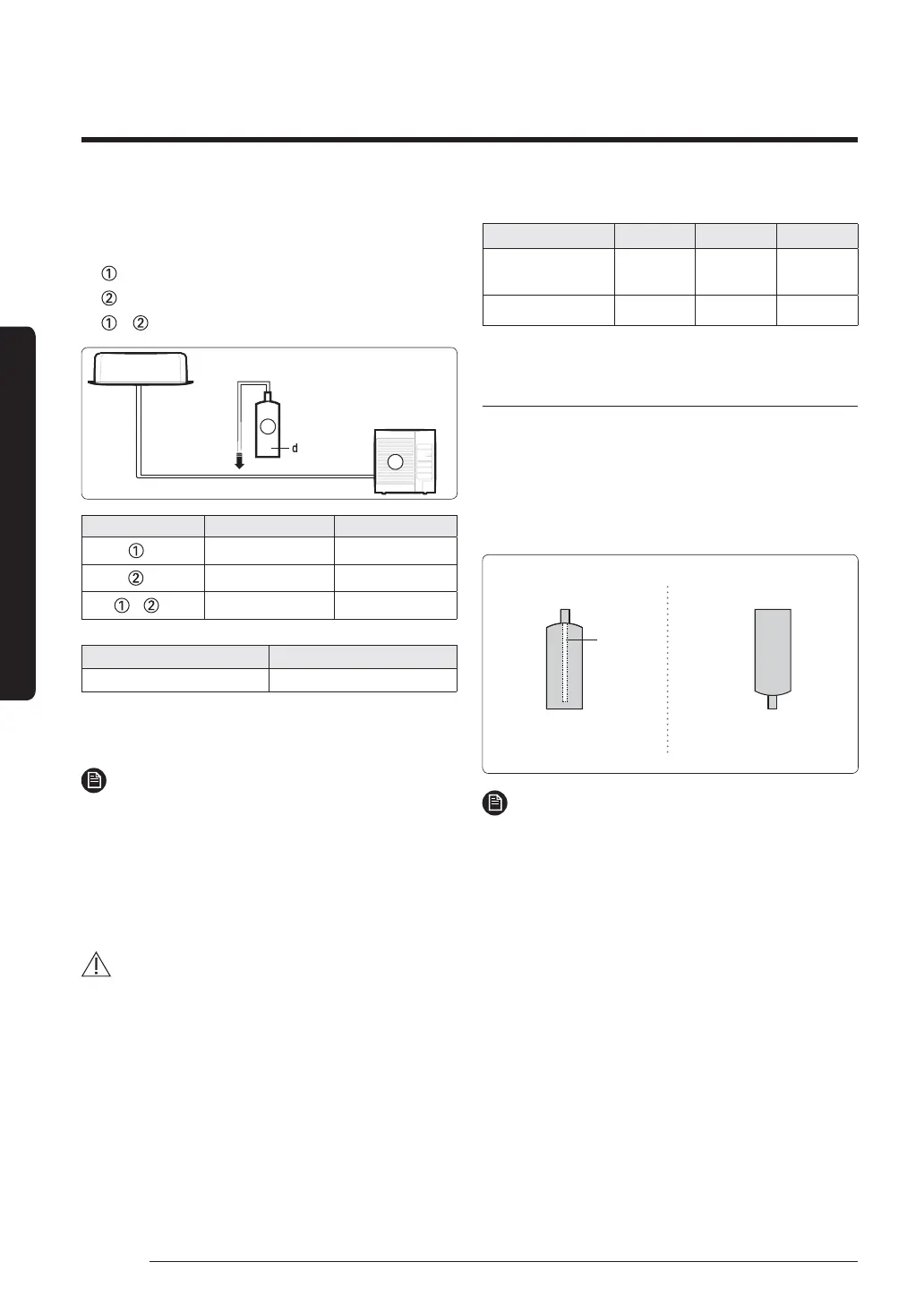
• Before recharging, check whether the cylinder has
a siphon or not. There are two ways to recharge the
refrigerant.
Charge the refrigerant turning
the cylinder upside down.
Cylinder with siphon Cylinder without siphon
Charge the refrigerant standing
the cylinder upright.
siphon
NOTE
• During the measuring operation of refrigerant
quantity added use an electronic balance. If cylinder
doesn’t have syphon, upset it.

 Loading...