EasyManua.ls Logo

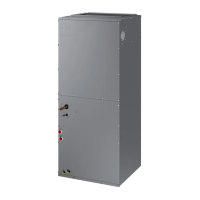
Samsung AHU Series User Manual

Samsung AHU Series
72 pages
To Next Page IconTo Next Page
Page #1 background imageLoading...
Page #1 background image
AHU SERIES CONTENTS
SYSTEM AIR CONDITIONER
AHU SERIES
1. Precautions
2. Product Specifications
3. Disassembly and Reassembly
4. Troubleshooting
5. PCB Diagram and Part List
6. Wiring Diagram
7. Reference Sheet
INDOOR UNIT OUTDOOR UNIT
Model :
AC018KNZDCH/AA
AC024KNZDCH/AA
AC030KNZDCH/AA
AC036KNZDCH/AA
AC042KNZDCH/AA
AC048KNZDCH/AA
AC054KNZDCH/AA
AC018JXADCH/AA
AC024JXADCH/AA
AC030JXADCH/AA
AC036JXADCH/AA
AC042JXADCH/AA
AC048JXADCH/AA
AC054KXADCH/AA
All manuals and user guides at all-guides.com
all-guides.com

Questions and Answers:

Samsung AHU Series Specifications

General IconGeneral
BrandSamsung
ModelAHU Series
CategoryAir Conditioner
LanguageEnglish

Summary

Precautions

Product Specifications

Disassembly and Reassembly

3-1 Indoor Unit Disassembly

3-2 Outdoor Unit Disassembly: AC018JXADCH

Outdoor Unit Disassembly: AC024/030JXADCH

Outdoor Unit Disassembly: AC024/030JXADCH (cont.)

Outdoor Unit Disassembly: AC036/042/048/054KXADCH

Outdoor Unit Disassembly: AC036/042/048/054KXADCH (cont.)

Troubleshooting

4-1 Indoor Display Error and Check Method

Guides for interpreting indoor unit LED error displays and initial troubleshooting steps.

4-1-1 Indoor unit LED lamp display at error detecting

Table detailing abnormal conditions and corresponding LED indicator patterns on the indoor unit.

4-1-2 Wired Remocon Error Display

List of error codes displayed on the wired remote controller and their explanations.

4-2 Troubleshooting by symptoms

4-2-1 Indoor temperature sensor (open/short)

Troubleshooting flowchart and resistance values for indoor temperature sensor faults.

4-2-2 Eva in and out sensor (open/short)

Troubleshooting flowchart and resistance values for EVA sensor faults.

4-2-3 Fan error

Diagnostic steps for fan motor errors, checking connections and foreign substances.

4-2-4 Terminal Block's Terminal Fuse(Open)

Procedure to check for an open terminal fuse in the terminal block and troubleshooting steps.

4-2-5 Outdoor's service valve(Clog)

Troubleshooting steps for a clogged outdoor service valve, including opening the valve.

4-2-6 EEPROM error

Procedure to resolve EEPROM errors by checking connections and replacing the PCB.

4-2-7 Option error

Steps to fix option errors by inputting the correct option code to the EEPROM PCB.

4-3 Setting the indoor unit option code

4-3-1 Setting an indoor unit address and installation option

Guide to setting the indoor unit's communication address using the wired remote controller.

Setting an indoor unit installation option

Instructions for setting the indoor unit's installation option code via the wired remote controller.

4-4 Items to be checked first

PCB Diagram and Part List

5-1 Indoor Unit

Diagrams and part identification for the main PCB of the indoor unit.

5-1-1 MAIN PCB Diagram

Detailed layout and component identification for the indoor unit's main printed circuit board.

5-2 Outdoor Unit

5-2-2 SUB PCB

5-2-3 MAIN PCB

5-2-4 INVERTER PCB

AC054KXADCH Inverter PCB

5-2-5 EMI PCB

Wiring Diagram

6-2 Outdoor Unit

Wiring Diagram for Outdoor: AC024-048JXADCH

Wiring Diagram for Outdoor: AC054KXADCH

7-2 Index of Model Name

Related product manuals