This document is an installation manual for the Samsung DVM S Air Conditioner, specifically for the AMMXVAFC Series and AMMXVAJC Series. It provides comprehensive instructions and safety precautions for installers.
Function Description
The Samsung DVM S air conditioner is a system designed for cooling and potentially heating (though the manual primarily focuses on cooling specifications for the MXVAFC series) multiple indoor units from a single or modular outdoor unit. It utilizes R-410A refrigerant, which is a quasi-azeotrope requiring liquid phase charging to prevent blend changes and potential malfunctions. The system is designed for a maximum pressure of 4.1MPa (594.6 psi), necessitating appropriate material and thickness for refrigerant piping. The outdoor unit combinations vary, supporting up to 64 indoor units with specific address ranges. The manual details the process of installing the outdoor unit, connecting refrigerant pipes, performing electrical wiring, conducting air tightness tests, vacuum drying, pipe insulation, and charging additional refrigerant. It also covers basic segment display, setting outdoor unit option switches, key functions, and post-installation checks and test operations, including an automatic refrigerant amount detection function.
Important Technical Specifications
- Refrigerant: R-410A.
- Maximum System Pressure: 4.1MPa (594.6 psi).
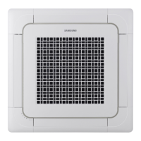
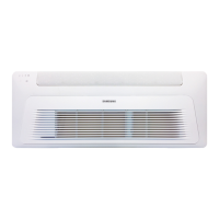
- Connectable Indoor Units: Maximum 64 units (addresses 0-63). Maximum 32 Wall-mount type indoor units with EEV (AM***NQDCH).
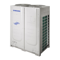
- Outdoor Unit Combinations (Cooling only - Standard Type AMMXVAFC/AZ Series):*
- AM080MXVAFC/AZ: 22.4 kW (76,400 Btu/h) nominal cooling, 11.2 kW (38,200 Btu/h) min, 29.1 kW (99,400 Btu/h) max, 14 connectable indoor units.
- AM100MXVAFC/AZ: 28.0 kW (95,500 Btu/h) nominal cooling, 14.0 kW (47,800 Btu/h) min, 36.4 kW (124,200 Btu/h) max, 18 connectable indoor units.
- AM120MXVAFC/AZ: 33.6 kW (114,600 Btu/h) nominal cooling, 16.8 kW (57,300 Btu/h) min, 43.7 kW (149,000 Btu/h) max, 21 connectable indoor units.
- AM140MXVAFC/AZ: 40.0 kW (136,500 Btu/h) nominal cooling, 20.0 kW (68,200 Btu/h) min, 52.0 kW (177,400 Btu/h) max, 26 connectable indoor units.
- AM160MXVAFC/AZ: 45.0 kW (153,500 Btu/h) nominal cooling, 22.5 kW (76,800 Btu/h) min, 58.5 kW (199,600 Btu/h) max, 29 connectable indoor units.
- Modular combinations extend up to AM800MXVAFC1AZ with 224.0 kW (764,400 Btu/h) nominal cooling and 64 connectable indoor units.
- Outdoor Unit Combinations (Cooling only - Standard Type AMMXVAFC Anti-Corrosion Series):* Similar capacity ranges as the standard type, with specific models like AM080MXVAFCAAZ up to AM560MXVAFCAAZ.
- Outdoor Unit Combinations (Cooling only - Compact Type AMMXVAFC Series):* Similar capacity ranges as the standard type, with specific models like AM080MXVAFC/AZ up to AM560MXVAFC2AZ.
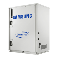
- Outdoor Unit Combinations (Cooling only - Compact Type AMMXVAJC Series):* Similar capacity ranges as the standard type, with specific models like AM080MXVAJC/AZ up to AM800MXVAJC2AZ.
- Refrigerant Pipe Length: Maximum 90m (295.28ft) for main pipe without size increase; beyond 90m, main pipe size must be increased by one grade. Total extended pipe length up to 1000m (3281ft) or less.
- Height Difference: Outdoor unit to indoor unit: 110m (361ft) (both higher and lower levels). Indoor unit to indoor unit: 50m (164ft) or less.
- Pipe Insulation: EPDM material insulator meeting specific density, dimensional change rate, absorption rate, thermal conduction rate, moisture transpiration factor, formaldehyde dispersion, and oxygen rate. Thickness varies by pipe diameter and humidity conditions (general or high humidity).
- Electrical Wiring: Requires exclusive circuit breaker (MCCB, ELB), proper grounding, and specified power cable types (polychloroprene sheathed flexible cord IEC: 60245 IEC 66 / CENELEC: H07RN-F). Power cable and communication cable must be installed separately using protection tubes.
- Outdoor Unit Base Ground: Minimum height 200mm (8inch), 1/50 slope for drainage. Must be strong enough to withstand unit weight and wind speed of 30m/s. Anti-vibration pad (t=20mm/0.78 inch or more) or frame recommended.
- Discharge Duct: Static pressure within 78.45 Pa (0.315 W.G).
Usage Features
- Y-Joints: Essential for optimal refrigerant distribution when connecting outdoor units in a module. T-joints are not to be used.
- Trial Operation: Mandatory via KEY MODE for normal operation after installation.
- Refrigerant Charging: R-410A must be charged in liquid phase. Additional refrigerant calculation is based on total liquid pipe length and individual indoor unit specifications.
- Outdoor Unit Option Switches: Allow for setting total number of installed indoor units, maximum capacity restriction for cooling operation, selecting outdoor unit address, silent mode, high-head condition setting, long-piping condition setting, energy control operation, channel address, and snow accumulation prevention control.
- Key Functions (K1, K2, K3, K4): Used for auto trial operation, refrigerant charging in cooling mode, pump down, checking refrigerant amount, discharge mode of DC link voltage, forced oil collection, inverter compressor checks, fan checks, and initial settings.
- Refrigerant Amount Detection Function: Automatically detects refrigerant amount in the system. Displays "K9 Ed" if supercooling degree is insufficient.
- Emergency Operation: Options for compressor malfunction and indoor unit communication error.
Maintenance Features
- Corrosion Protection: For installations near the seashore, a protection wall is recommended, and periodic cleaning with water is required to remove salinity. Anti-corrosion treatment (e.g., R-Pro, water repellent grease and wax) is advised every 3 months.
- Pipe Sealing: Important to prevent foreign materials or water from entering pipes during storage and installation.
- Nitrogen Flushing Welding: Essential during pipe welding to prevent oxidation and damage to compressor and valves.
- Gas Leak Detection: Use a designated solution for gas leakage detection after welding; avoid solutions with sulfuric ingredients.
- Vacuum Drying: Required to remove moisture from pipes using a vacuum pump capable of -100.7kPa (5 Torr).
- Service Valve: Must be fully open after refrigerant charging to prevent damage to important parts.
- Power Disconnection: Power must be cut off for at least 15 minutes before replacing/repairing PCBs to allow DC voltage to discharge.
- System Protection: The product operates in protection mode below 0°C (32°F); cutting off power can cause damage.
- Installation Report: Installers must complete a service history report after installation.
- Troubleshooting: Manual provides steps for E503, E505, E506 errors, including checking service valves, refrigerant quantity, and pressure sensors.