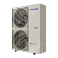
Do you have a question about the Samsung AM050KXMDEC and is the answer not in the manual?
Details on outdoor unit structure, fan motor, heat exchanger, and inter-cooler.
Comprehensive specifications including power, compressor, fan, pipe, and electrical details.
Lists essential tools required for disassembly and reassembly procedures.
Step-by-step instructions for disassembling specific outdoor unit models.
Specific disassembly steps tailored for the KXMDEC model series.
Overview of error display and a comprehensive list of error codes.
Diagnostic procedures for various error symptoms and codes.
Visual representation and labeling of the outdoor unit's printed circuit boards.
Electrical wiring schematic for single-phase outdoor unit configurations.
Electrical wiring schematic for three-phase outdoor unit configurations.
Diagrams of refrigerant flow and explanation of model nomenclature codes.
Guides for performing operational checks, troubleshooting 'Undetermined' results, and refrigerant detection.
| Model | AM050KXMDEC |
|---|---|
| Cooling Capacity | 5.0 kW |
| Heating Capacity | 5.6 kW |
| Refrigerant | R410A |
| Power Supply | 220-240V, 50Hz |
| Air Flow (High) | 12.5 m³/min |
| Net Weight (Indoor Unit) | 11.5 kg |
| Energy Efficiency Ratio (EER) | 3.21 |
| Operating Temperature (Cooling) | 18 ~ 43 °C |


 Loading...