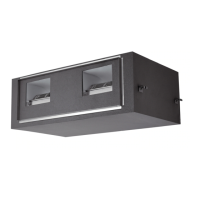
Do you have a question about the Samsung AM200KXVAGH/ET and is the answer not in the manual?
General guidelines for servicing the air conditioner, including part usage, connections, and assembly.
Essential safety practices to prevent electrical shock, fire hazards, and proper grounding.
Safety and environmental guidelines for handling refrigerant gas release and container management.
Detailed technical specifications for various product models.
Comprehensive specifications for the outdoor unit, including capacity, power, and dimensions.
Step-by-step instructions for disassembling and reassembling various outdoor unit components.
Important precautions and procedures for safely exchanging a compressor.
Information on special operations and service modes for the outdoor unit.
Detailed guide to special operations like refrigerant charging, trial, and vacuuming.
Provides troubleshooting steps for various system symptoms and error codes.
A flowchart for performing the outdoor unit's Auto Trial Operation and checking its status.
Troubleshooting steps for when the main PCB shows no power or the 7-seg display is blank.
Steps to diagnose and resolve communication errors occurring during tracking.
Detailed diagram and pin assignments for the main PCB assembly.
Diagram and pin assignments for the main PCB hub assembly.
Diagram and pin assignments for the inverter PCB assembly.
Diagram and pin assignments for the fan PCB assembly.
Diagram and pin assignments for the EMI PCB assembly.
Wiring diagram for specific outdoor unit models in the FXV/JXV/KXVA/KXVG series.
Wiring diagram for specific higher capacity outdoor unit models.
Illustrates refrigerant flow during cooling operation in Heat Recovery mode.
Illustrates refrigerant flow for main cooling in Heat Recovery mode.
Illustrates refrigerant flow during heating operation in Heat Recovery mode.
Procedures and guidelines for performing the Auto Trial Operation.
Steps to troubleshoot specific "Undetermined" errors encountered during Auto Trial Operation.
| Brand | Samsung |
|---|---|
| Model | AM200KXVAGH/ET |
| Category | Air Conditioner |
| Language | English |


 Loading...