E-33
ENGLISH
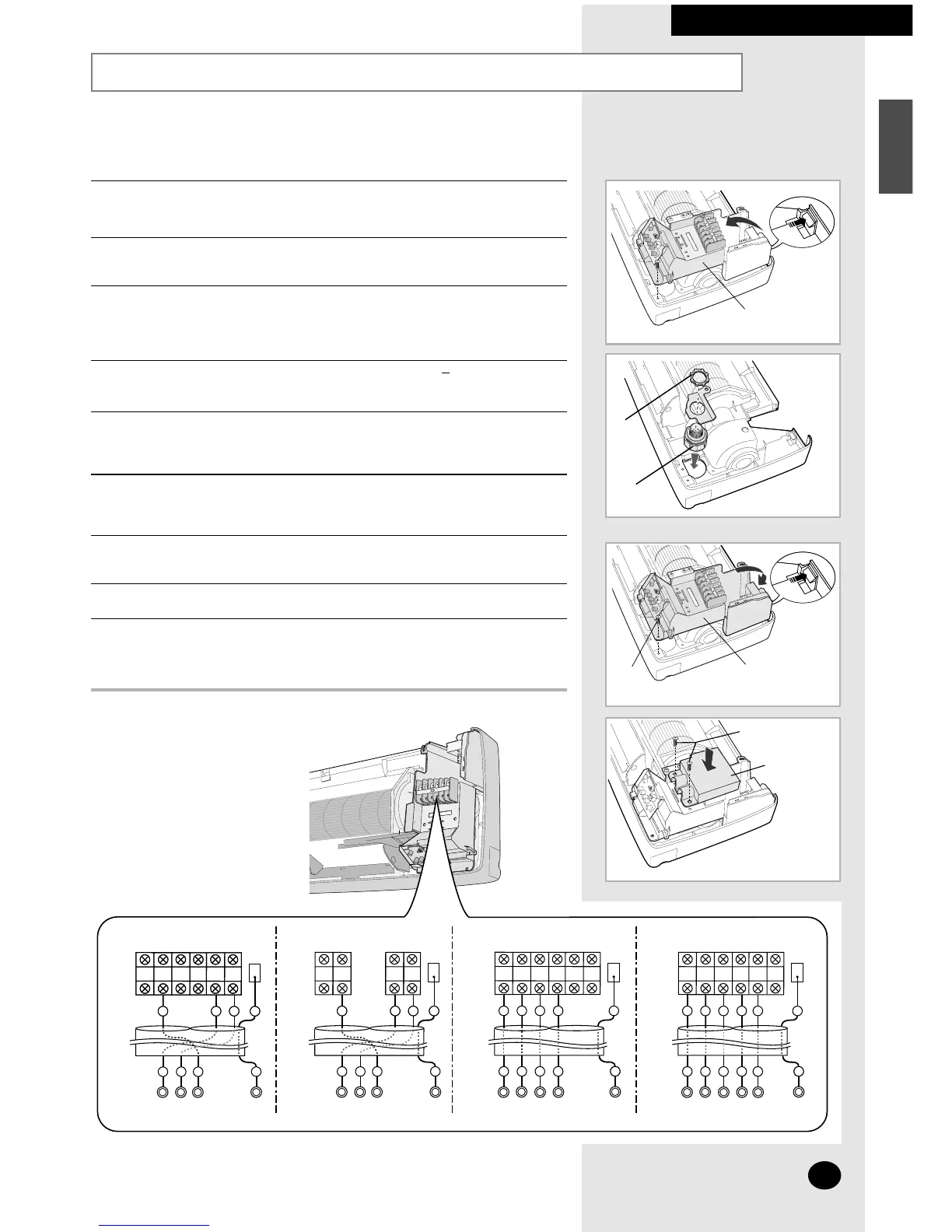
Connecting the Assembly Cable (cont.)
INSTALLING THE INDOOR UNIT
5 Detach the control box from the indoor unit.
9 Reinstall the control box, then tighten the C screw.
➢ The C screw is provided with this manual.
11 Replace the front panel, carefully tightening the screws.
12 Reinstall the front grille.
13 For further details on how to plug the other end of the assembly cable into
the outdoor unit, refer to page 37.
6 Install the conduit kit. (The conduit kit is optional)
7 Pass the assembly cable through the rear of the indoor unit and connect the
assembly cable to terminals as shown in the figure.
➢ Each wire is labelled with the corresponding terminal number.
8 Pass the other end of the cable through the 65mm( inch) hole in the
wall.
10 Install the D terminal block cover, tightening the E screws.
➢
The D terminal block cover and E screws are provided with this manual.
2
9
16
 Loading...