EasyManua.ls Logo

Samsung AW07FASEA User Manual

Samsung AW07FASEA
61 pages
To Next Page IconTo Next Page
Page #1 background imageLoading...
Page #1 background image
ROOM AIR CONDITIONER
AW0690A
AW0790A
AW07FASAA
AW07FASBA
AW07FASEA
AW0890A
AW09FASBA
AW09FASEA
AW09FBSEA
AW1090A
AW10FAJAA
AW10FAJBA
AW12FAJAA
AW12FAJBA
AW12FAJDA
AW12FAJEA
AW12FBJEA
AW1290A
AW1480A
AW14FAMBA
AW1880A
AW18FAMBA
AW18FAMCA
AW18FAMBB
AWT18FAMDA
AW18FAMEA
AW18FBMEA
AW24FAMBB
AW24FAMBA
AW24FAMCA
AWT24FAMEA
AW2490D
AIR CONDITIONER CONTENTS
1. Precautions
2. Product Specifications
3. Installation and Operating
Instructions
4. Disassembly and Reassembly
5. Troubleshooting
6. Exploded Views and Parts List
7. Block Diagram
8. PCB Diagram
9. Wiring Diagram
10. Schematic Diagrams
SERVICE
Manual
DB68-02477A(2)-co 3/20/02 1:39 PM Page 2
Question and Answer IconNeed help?

Do you have a question about the Samsung AW07FASEA and is the answer not in the manual?

Samsung AW07FASEA Specifications

General IconGeneral
BrandSamsung
ModelAW07FASEA
CategoryAir Conditioner
LanguageEnglish

Summary

1. Precautions

2. Product Specifications

2-2 Dimensions

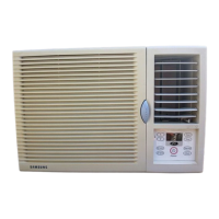
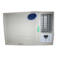
Physical dimensions of the main unit for different types A, B, and C.

3. Installation and Operating Instructions

3-1 Installation

Procedures and considerations for selecting an installation site.

3-2 Function Description

Explanation of the various operating modes and features.

3-3 Remocon Control

Details on operating the air conditioner using the remote control.

4. Disassembly and Reassembly

4-1 Compressor Replacement Flow Chart

Flowchart for replacing the compressor, including diagnostic steps.

4-2 Disassembly and Reassembly Procedure

Detailed disassembly steps for unit types A, B, and C.

5. Troubleshooting

5-1 Basic Checkpoints for Troubleshooting

Initial checks to perform before proceeding with symptom-based troubleshooting.

5-2 Troubleshooting by Symptom

Troubleshooting guides based on specific operational problems.

6. Exploded View and Parts List

6-1 Main unit (Type "A")

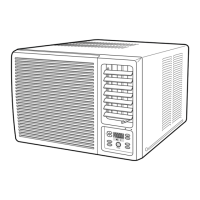
Exploded view of the Type A main unit.

Part List (Type "A")

Comprehensive list of parts for Type A models.

6-2 Main unit (Type "B")

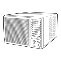
Exploded view of the Type B main unit.

Part List (Type "B")

Comprehensive list of parts for Type B models.

6-3 Main unit (Type ā€œCā€)

Exploded view of the Type C main unit.

Part List (Type "C")

Comprehensive list of parts for Type C models.

7. Block Diagram

7-1 Refrigerating Cycle Block Diagram

Schematic of the refrigerant flow and components.

7-2 Basic Structure

Overview of the unit's control system architecture.

7-2-2 Micom Pin Assignment

Mapping of microcontroller pins to their functions and connections.

8. PCB Diagram

8-1 ASS'Y Main PCB (Code No ; DB93-00407A, B, D)

Detailed diagram of the main PCB assembly with component references.

9. Wiring Diagram

9-1 Wiring Diagram - Model Overview

Electrical wiring schematics showing connections for various models.

10. Schematic Diagrams

10-1 Main PCB

Schematic diagram of the main PCB for specific models.

10-2 Main PCB

Schematic diagram of the main PCB for other specific models.

10-3 Remote Control

Schematic diagram of the remote control's circuitry.

Related product manuals